
GRD44B-5R User Manual: Difference between revisions
No edit summary |
No edit summary |
||
| (31 intermediate revisions by the same user not shown) | |||
| Line 19: | Line 19: | ||
Type the command '''Ipconfig''' | Type the command '''Ipconfig''' | ||
[[File:How to connect with the SILBO RB44 application.png|frameless| | [[File:How to connect with the SILBO RB44 application.png|frameless|1024x1024px]] | ||
It will provide the Ip address/url of that device through which the application can be accessed. | It will provide the Ip address/url of that device through which the application can be accessed. | ||
[[File:Connecting_via_LAN_RB44.png|frameless| | [[File:Connecting_via_LAN_RB44.png|frameless|1024x1024px]] | ||
== Log In == | == Log In == | ||
| Line 30: | Line 30: | ||
It will show the log in page of the application. | It will show the log in page of the application. | ||
[[File:Login to device.png|frameless| | [[File:Login to device.png|frameless|1024x1024px]] | ||
Give the valid credentials for the username and password to login to the application page. | Give the valid credentials for the username and password to login to the application page. | ||
| Line 40: | Line 40: | ||
The “Status” landing page shows all the detailed specification of the device like system, memory storage and connection tracking etc. | The “Status” landing page shows all the detailed specification of the device like system, memory storage and connection tracking etc. | ||
[[File:GRD44B-5R Dashboard.png|frameless| | [[File:GRD44B-5R Dashboard.png|frameless|1024x1024px]] | ||
The application is divided in to 8 Modules. | The application is divided in to 8 Modules. | ||
| Line 64: | Line 64: | ||
* Kernel Log | * Kernel Log | ||
[[File:GRD44B-5R Info Section.png| | [[File:GRD44B-5R Info Section.png|1024x1024px]] | ||
=== 1.1 Overview === | === 1.1 Overview === | ||
In overview module it displays all the specification categorically of a device like System, Memory, storage, Connection tracking, DHCP Lease. | In overview module it displays all the specification categorically of a device like System, Memory, storage, Connection tracking, DHCP Lease. | ||
[[File:GRD44B-5R Dashboard.png| | [[File:GRD44B-5R Dashboard.png|1024x1024px]] | ||
'''System:''' | '''System:''' | ||
| Line 75: | Line 75: | ||
In this section it displays the hardware configured specification of the device. | In this section it displays the hardware configured specification of the device. | ||
[[File:GRD44B-5R System Section.png| | [[File:GRD44B-5R System Section.png|975x975px]] | ||
The specifications details are as follows, | The specifications details are as follows, | ||
| Line 86: | Line 86: | ||
|1 | |1 | ||
|Hostname | |Hostname | ||
| | |45A27240005 | ||
|This field displays the router serial number of the device | |This field displays the router serial number of the device | ||
|- | |- | ||
| Line 96: | Line 96: | ||
|3 | |3 | ||
|Firmware Version and IPK Version | |Firmware Version and IPK Version | ||
|1. | |1.17_1.15 | ||
|This field displays the firmware version and IPK version | |This field displays the firmware version and IPK version | ||
|- | |- | ||
|4 | |4 | ||
|Application Firmware version and IPK version | |Application Firmware version and IPK version | ||
|1.03_1. | |1.03_1.13 | ||
|This field displays the software version of the device. | |This field displays the software version of the device. | ||
|- | |- | ||
| Line 107: | Line 107: | ||
|Kernel Version | |Kernel Version | ||
|4.14.180 | |4.14.180 | ||
|This field | |This field displays the kernel version of the device | ||
|- | |- | ||
|6 | |6 | ||
|Local Time | |Local Time | ||
| | |Wednesday, December 18, 2024 at 12:56:00 PM | ||
|This field displays the local time | |This field displays the local time | ||
|- | |- | ||
|7 | |7 | ||
|Uptime | |Uptime | ||
| | |5h 27m 5s | ||
|This field displays the uptime of the device | |This field displays the uptime of the device | ||
|- | |- | ||
|8 | |8 | ||
|Load Average | |Load Average | ||
|0. | |0.31 0.27 0.19 | ||
|This field | |This field displays the average load | ||
|} | |} | ||
'''Memory:''' | '''Memory:''' | ||
| Line 128: | Line 128: | ||
In this section it displays the memory configured specification of the device. | In this section it displays the memory configured specification of the device. | ||
[[File:IAB44C Memory Section.png| | [[File:IAB44C Memory Section.png|1024x1024px]] | ||
The specifications details are as follows. | The specifications details are as follows. | ||
{| class="wikitable" | {| class="wikitable" style="height:auto; width:100%; text-align:center;" | ||
!SN | |||
!Field name | |||
!Sample value | |||
!Description | |||
|- | |- | ||
|1 | |1 | ||
| Line 163: | Line 163: | ||
In this section it displays the status of storage as root and temporary usage specification of the device. | In this section it displays the status of storage as root and temporary usage specification of the device. | ||
[[File:IAB44C Storage Section.png| | [[File:IAB44C Storage Section.png|975x975px]] | ||
| Line 188: | Line 188: | ||
In this section you can monitor IPv4 WAN status. | In this section you can monitor IPv4 WAN status. | ||
[[File:IPv4 Wan Status.png| | [[File:IPv4 Wan Status.png|1024x1024px]] | ||
The specifications details are as follows. | The specifications details are as follows. | ||
| Line 229: | Line 229: | ||
This section displays SIM details only when the SIM card is active. | This section displays SIM details only when the SIM card is active. | ||
[[File:IAB44C Sim Information.png| | [[File:IAB44C Sim Information.png|1024x1024px]] | ||
'''Connection Tracking:''' | '''Connection Tracking:''' | ||
| Line 235: | Line 235: | ||
In this section it displays the status of connection tracking for the device. | In this section it displays the status of connection tracking for the device. | ||
[[File:Connection Tracking.png| | [[File:Connection Tracking.png|1024x1024px]] | ||
The specifications details are as follows. | The specifications details are as follows. | ||
| Line 255: | Line 255: | ||
In this section it displays the DHCP lease of the temporary assignment of an IP address to a device on the network. | In this section it displays the DHCP lease of the temporary assignment of an IP address to a device on the network. | ||
[[File:IAB44C DHCP Leases.png| | [[File:IAB44C DHCP Leases.png|1024x1024px]] | ||
The specifications details are below. | The specifications details are below. | ||
| Line 289: | Line 289: | ||
This page provides on screen System logging information. In this page the user gets to view the system logs. | This page provides on screen System logging information. In this page the user gets to view the system logs. | ||
[[File:System | [[File:GRD44B-5R System log.png|1024x1024px]] | ||
=== 1.3 Kernel Log === | === 1.3 Kernel Log === | ||
| Line 296: | Line 296: | ||
In this page the user gets to view the Kernel logs. | In this page the user gets to view the Kernel logs. | ||
[[File:Kernel Log.png| | [[File:GRD44B 5R Kernel Log.png|1024x1024px]] | ||
| Line 305: | Line 306: | ||
* Network | * Network | ||
* VLAN | |||
* Sim Switch | * Sim Switch | ||
* | * Multi-WAN | ||
* VPN | * VPN | ||
* Firewall | * Firewall | ||
* Loopback Rule | * Loopback Rule | ||
* VRRP | |||
* Remote Monitoring | * Remote Monitoring | ||
* Tunnel | * Tunnel | ||
[[File:Settings.png| | [[File:GRD44B 5R Settings.png|1024x1024px]] | ||
=== 2.1 Network === | === 2.1 Network === | ||
In this section the user does all the setting related configuration with reference to network like Ethernet Setting, Cellular Setting, Band lock and Operator Lock, Wi-Fi, Guest Wi-Fi, Wireless Schedule, SMS Setting, Loopback IP. | In this section the user does all the setting related configuration with reference to network like Ethernet Setting, Cellular Setting, Band lock and Operator Lock, Wi-Fi, Guest Wi-Fi, Wireless Schedule, SMS Setting, Loopback IP. | ||
[[File: | [[File:GRD44B-5R Network configuration.png|1024x1024px]] | ||
'''Ethernet Setting:''' | '''Ethernet Setting:''' | ||
| Line 324: | Line 327: | ||
In this page it will display all the configured port that is attached with the device. | In this page it will display all the configured port that is attached with the device. | ||
For this device 5 ports are configured. Ethernet mode can be configured as WAN and as LAN as well. Ethernet | For this device 5 ports are configured. | ||
Ethernet mode can be configured as WAN and as LAN as well. | |||
Ethernet WAN Connection settings can be configured as DHCP, Static and PPOE. | |||
[[File:GRD44B-5R Ethernet settings.png|1024x1024px]] | |||
'''EDIT:''' | |||
To add a new Interface, click on ‘Add’. | |||
To edit the existing device the user needs to click on the edit option. | |||
Once the changes are done click on the update button to save all the changes. | |||
Click on the deleted button to delete the existing device detail. | |||
[[File:GRD44B-5R Network configuration edit.png|1024x1024px]] | |||
Specification details are given below: '''Type: WAN''' | |||
{| class="wikitable" | {| class="wikitable" | ||
|SN | |SN | ||
|Field | |Field Name | ||
|Sample | |Sample Value | ||
|Description | |Description | ||
|- | |- | ||
|1 | |1 | ||
| | |Physical Device | ||
| | |Ex: eth0.5 | ||
|This | |This indicates a network interface on which our network is connected. This setting is by default (Editable). | ||
|- | |- | ||
|2 | |2 | ||
| | |Type | ||
| | |'''WAN'''/LAN | ||
|This designates whether the interface is part of the WAN or LAN. | |||
WAN: Connects the device to the internet. | |||
LAN: Connects the device to the internal network. | |||
|- | |||
| colspan="4" | '''Protocol: Static''' | |||
|- | |- | ||
|3 | |3 | ||
| | |Static IP Address | ||
|Ex: 192.168.1.10 | |||
|The manually assigned IP address for the interface. | |||
| | |||
| | |||
|- | |- | ||
|4 | |4 | ||
| | |Static Netmask | ||
|255.255.255.0 | |Ex: 255.255.255.0 | ||
| | |Subnet mask corresponding to the IP address. | ||
|- | |- | ||
|5 | |5 | ||
| | |Static Gateway | ||
| | |Ex: 192.168.1.1 | ||
| | |The IP address of the gateway (router) that the interface will use to send traffic outside its own subnet. | ||
|- | |||
| colspan="4" | '''Protocol: DHCP''' | |||
|- | |- | ||
|6 | |6 | ||
| | |DHCP Gateway | ||
| | |Ex: 10.1.1.1 | ||
| | |The IP address of the DHCP server (often the same as the router or gateway). | ||
|- | |- | ||
| | | colspan="4" | '''Protocol: PPPoE''' | ||
| | |||
|- | |- | ||
| | |7 | ||
|Username | |||
|Any Name | |||
|The username provided by your ISP for PPPoE authentication. | |||
|- | |||
|8 | |||
|Password | |||
|***** | |||
|The password provided by your ISP for PPPoE authentication. | |||
|- | |||
|9 | |||
|Access Concentrator | |||
| | |||
|Typically, the name of the ISP's PPPoE server. | |||
|- | |||
|10 | |||
|Service Name | |||
| | |||
|Sometimes required by ISPs, this field specifies a particular service offered by the ISP. | |||
|- | |||
|11 | |||
|Gateway | |||
|Ex: 0.0.0.0 | |||
|The IP address used as the default route. | |||
|- | |||
|12 | |||
|MAC Address | |||
|Ex: D0:93:95:B0:98:6B | |||
|The hardware (MAC) address of the network interface. This is unique to every network device. | |||
|- | |||
|13 | |||
|Override MAC Address | |||
|Ex: D0:93:95:B0:98:6B | |||
|This field allows you to manually set a different MAC address if needed. | |||
If left blank, the default MAC address is used. | |||
|- | |||
|14 | |||
|Create Firewall Zone | |||
|Enable/Disable | |||
|You can assign this interface to a particular firewall zone, which determines its access rules (e.g., WAN zone for internet traffic, LAN zone for internal traffic). | |||
|- | |||
| colspan="4" |'''Advanced Settings: Enable/Disable''' | |||
|- | |||
|15 | |||
|Broadcast | |||
|Ex: 192.168.123.34 | |||
|Broadcast address for the network, typically calculated based on the IP and subnet mask. | |||
|- | |||
|16 | |||
|Override MTU | |||
|Ex: 1500 | |||
|MTU size controls the maximum packet size that can be sent over the network. | |||
Default is usually 1500 bytes. | |||
|- | |||
|17 | |||
|Delegate | |||
|Enable/Disable | |||
|If checked, it allows delegation of prefixes for IPv6, often left unchecked unless needed. | |||
|- | |||
|18 | |||
|Force Link | |||
|Enable/Disable | |||
|Forces the interface to be up even if no physical link is detected. | |||
|- | |||
|19 | |||
|IPv4 Route Table | |||
|Enable/Disable | |||
|This field is used to specify static routes for IPv4. | |||
|- | |||
|20 | |||
|Table No. | |||
|'''254''': Default main routing table. | |||
'''100''': Custom routing table for specific purposes. | |||
|'''Default Table (Main Table)''': Usually, there is a default routing table (often Table No. 254 or 255) where all the routes are stored by default. | |||
'''Custom Table''': You can specify a different table number if you are managing multiple routing policies (e.g., VoIP traffic, VPN traffic). | |||
| | |} | ||
'''Type: LAN''' | |||
[[File:Grd44b 5r LAN config.png|1024x1024px]] | |||
Specification details are given below: | |||
{| class="wikitable" | |||
|SN | |||
|Field Name | |||
|Sample Value | |||
{| class="wikitable" | |||
|SN | |||
|Field | |||
|Sample | |||
|Description | |Description | ||
|- | |- | ||
|1 | |1 | ||
| | |Physical Device | ||
| | |Ex: eth0.1 | ||
|This | |This is the network interface identifier. | ||
|- | |- | ||
|2 | |2 | ||
| | |Type | ||
| | |WAN/'''LAN''' | ||
|This designates whether the interface is part of the WAN or LAN. | |||
WAN: Connects the device to the internet. | |||
LAN: Connects the device to the internal network. | |||
|- | |- | ||
|3 | |3 | ||
| | |Protocol | ||
| | |Static | ||
|This | |This means that the IP address, netmask, and other network settings are manually configured rather than being automatically assigned by a DHCP server. | ||
|- | |- | ||
|4 | |4 | ||
| | |IP Address | ||
| | |Ex: 192.168.10.1 | ||
|This | |This is the static IP address assigned to the interface. It acts as the gateway IP address for devices connected to this LAN. | ||
|- | |- | ||
|5 | |5 | ||
| | |Static Netmask | ||
| | |Ex: 255.255.255.0 | ||
|This | |This is the subnet mask for the network. | ||
|- | |- | ||
|6 | |6 | ||
| | |MAC Address | ||
| | |Ex: D0:93:95:B0:98:6C | ||
|This | |This is the hardware (MAC) address of the network interface, which uniquely identifies this device on the network. | ||
|- | |- | ||
|7 | |7 | ||
|DNS Server Address | |Override MAC Address | ||
|8.8.8.8 | | | ||
|This | |This allows you to manually enter a different MAC address if needed. | ||
|- | |||
|8 | |||
|Enable DNS | |||
|Enable/Disable | |||
|If this option is enabled, the interface will act as a DNS resolver for the devices on the LAN, using the specified DNS server. | |||
|- | |||
|9 | |||
|DNS Server Address | |||
|Ex: 8.8.8.8 | |||
|This is the IP address of the DNS server that will be used by devices on the LAN to resolve domain names to IP addresses. | |||
More than one DNS Address can be added. | |||
|- | |||
|10 | |||
|Enable DHCP Server | |||
|Enable/Disable | |||
|If enabled, this setting allows the interface to function as a DHCP server, automatically assigning IP addresses to devices connected to the LAN. | |||
|- | |||
|11 | |||
|DHCP Start Address | |||
|70 | |||
|The DHCP server will begin assigning IP addresses starting from 192.168.10.70 | |||
|- | |||
|12 | |||
|DHCP Limit | |||
|100 | |||
|This specifies the number of IP addresses the DHCP server can assign. Starting at 192.168.10.70 and with a limit of 100, the server can assign addresses up to 192.168.10.169. | |||
|- | |||
|13 | |||
|Lease Time Duration | |||
|Hours-(H) | |||
Minutes-(M) | |||
''' | Seconds-(S) | ||
|'''Hours-(H)''': This indicates that the lease time for each IP address assignment is measured in hours. | |||
'''Minutes-(M):''' This indicates that the lease time for each IP address assignment is measured in minutes. | |||
''' | '''Seconds-(S):''' This indicates that the lease time for each IP address assignment is measured in seconds. | ||
|- | |||
|14 | |||
|Lease Time | |||
|12 | |||
|The DHCP lease time is set to 12 hours. After this period, a device must renew its IP address lease with the DHCP server to continue using the assigned IP address. | |||
| | |||
| | |||
| | |||
|- | |- | ||
| | |15 | ||
| | |Create Firewall Zone | ||
| | |Enable/Disable | ||
| | |You can assign this interface to a particular firewall zone, which determines its access rules (e.g., WAN zone for internet traffic, LAN zone for internal traffic). | ||
|- | |- | ||
| | |16 | ||
|SW_LAN | |Internet Over SW_LAN | ||
| | |Enable/Disable | ||
| | |Allow all outbound traffic from the LAN to the internet. | ||
|- | |- | ||
| | | colspan="4" |'''Advanced Settings: Enable/Disable''' | ||
| | |||
|- | |- | ||
| | |17 | ||
| | |Broadcast | ||
| | |Ex: 192.168.123.34 | ||
| | |Broadcast address for the network, typically calculated based on the IP and subnet mask. | ||
|- | |- | ||
| | |18 | ||
| | |Override MTU | ||
| | |Ex: 1500 | ||
| | |MTU size controls the maximum packet size that can be sent over the network. | ||
Default is usually 1500 bytes. | |||
|- | |||
|19 | |||
|Delegate | |||
|Enable/Disable | |||
|If checked, it allows delegation of prefixes for IPv6, often left unchecked unless needed. | |||
|- | |||
|20 | |||
|Force Link | |||
|Enable/Disable | |||
|Forces the interface to be up even if no physical link is detected. | |||
|- | |||
|21 | |||
|IPv4 Route Table | |||
|Enable/Disable | |||
|This field is used to specify static routes for IPv4. | |||
|} | |||
Save and Update once configuration changes have been made. | |||
'''Relay Server:''' | |||
A relay server typically functions in a network to forward requests (usually DHCP or DNS) from clients to | |||
a designated server when the server is on a different network segment. | |||
[[File:GRD44B 5R Relay server.png|1024x1024px]] | |||
'''EDIT:''' | |||
To edit the existing device the user needs to click on the edit option. | |||
Once the changes are done click on the save button to save all the changes. | |||
Click on the deleted button to delete the existing device detail. | |||
[[File:GRD44B 5R Relay server edit.png|1024x1024px]] | |||
Specification details are given below: | |||
{| class="wikitable" | {| class="wikitable" | ||
|SN | |SN | ||
|Field | |Field Name | ||
|Sample | |Sample Value | ||
|Description | |Description | ||
|- | |- | ||
|1 | |1 | ||
| | |Interface | ||
| | |1.) eth0.1 | ||
| | |||
2.) ra0 | |||
|1) eth0.1 typically represents a VLAN where the relay will listen for client requests. | |||
2) If your device is broadcasting a Wi-Fi network on the ra0 interface, any DHCP or DNS relay settings will apply to devices connected via this wireless interface. | |||
|- | |- | ||
|2 | |2 | ||
| | |Start IP Address | ||
| | |Ex: 192.168.10.100 | ||
|This is the beginning IP address of the range that will be leased out to clients. | |||
| | |||
|- | |- | ||
|3 | |3 | ||
|Cellular Modem 1 | |End IP Address | ||
|QuectelEC200A | |Ex: 192.168.10.150 | ||
|This field displays the modem name. | |An IP address that is in the same subnet as the Start IP Address and allows sufficient addresses to be leased. | ||
|- | |||
|4 | |||
|Netmask | |||
|Ex: 255.255.255.0 | |||
|A valid subnet mask such as 255.255.255.0 (for a /24 network), or 255.255.0.0 (for a /16 network). | |||
|- | |||
|5 | |||
|Lease Time | |||
|For a 24-hour lease time, set this value to 86400. | |||
|This is the amount of time that an IP address is assigned to a client before it needs to request a renewal from the DHCP server. | |||
|} | |||
Save and update. | |||
'''Cellular Setting:''' | |||
In this page, the user needs to configure the various details with respect to the SIM. | |||
Select single cellular single sim where the user must configure the APN details of the sim used for the router device. The Configurations can be done based on the SIM usage, with respect to IPV4 or IPV6. | |||
[[File:GRD44B 5R Cellular settings.png|1024x1024px]] | |||
Specification details are given below: | |||
{| class="wikitable" | |||
|SN | |||
|Field name | |||
|Sample value | |||
|Description | |||
|- | |||
|1 | |||
|Cellular Enable | |||
|Checkbox | |||
|Check this box to enable cellular functionality. | |||
|- | |||
|2 | |||
|Cellular Operation Mode | |||
|1.) Single Cellular with Dual Sim | |||
2.) Single Cellular with Single SIM | |||
|1.) This mode allows you to use one cellular modem with two SIM cards. | |||
2.) This mode allows you to use one cellular modem with single SIM card. | |||
|- | |||
|3 | |||
|Cellular Modem 1 | |||
|QuectelEC200A | |||
|This field displays the modem name. | |||
|- | |- | ||
|4 | |4 | ||
| Line 592: | Line 741: | ||
|- | |- | ||
|10 | |10 | ||
|SIM 1 MTU | |||
|Ex: 1500 (a common MTU size) | |||
|'''MTU (Maximum Transmission Unit)''' defines the largest size of a data packet that can be transmitted over the network. | |||
|- | |||
|11 | |||
|Choose SIM 2 APN Mode | |Choose SIM 2 APN Mode | ||
|1.) Auto | |1.) Auto | ||
| Line 600: | Line 754: | ||
2.) Choose manual to enter the APN settings manually in case of M2M SIM cards. | 2.) Choose manual to enter the APN settings manually in case of M2M SIM cards. | ||
|- | |- | ||
| | |12 | ||
|SIM 2 Access Point Name | |SIM 2 Access Point Name | ||
|airtelgprs.com | |airtelgprs.com | ||
|Enter the APN provided by your cellular service provider in case of M2M sim. For regular sim cards APN name will be displayed automatically. | |Enter the APN provided by your cellular service provider in case of M2M sim. For regular sim cards APN name will be displayed automatically. | ||
|- | |- | ||
| | |13 | ||
|SIM 2 PDP Type | |SIM 2 PDP Type | ||
|IPV4 | |IPV4 | ||
|Choose the PDP type, which is typically either IPv4 or IPv6 depending on the sim card. | |Choose the PDP type, which is typically either IPv4 or IPv6 depending on the sim card. | ||
|- | |- | ||
| | |14 | ||
|SIM 2 Username | |SIM 2 Username | ||
| | | | ||
|Enter the username if required by the APN. Leave blank if not required. | |Enter the username if required by the APN. Leave blank if not required. | ||
|- | |- | ||
| | |15 | ||
|SIM 2 Password | |SIM 2 Password | ||
| | | | ||
|Enter the password if required by the APN. Leave blank if not required. | |Enter the password if required by the APN. Leave blank if not required. | ||
|- | |- | ||
| | |16 | ||
|SIM 2 Authentication Protocol | |SIM 2 Authentication Protocol | ||
|None | |None | ||
|Choose the authentication protocol. Options typically include None, PAP, or CHAP. | |Choose the authentication protocol. Options typically include None, PAP, or CHAP. | ||
|- | |- | ||
| | |17 | ||
|SIM 2 MTU | |||
|Ex: 1500 (a common MTU size) | |||
|'''MTU (Maximum Transmission Unit)''' defines the largest size of a data packet that can be transmitted over the network. | |||
|- | |||
|18 | |||
|Primary SIM Switchback Enable | |||
|Enable/Disable | |||
|When enabled, the device will automatically switch back to the primary SIM (SIM 1) after switching to SIM 2, under certain conditions (e.g., SIM 1 regains network availability). | |||
|- | |||
|19 | |||
|Primary SIM Switchback Time (In Minutes) | |Primary SIM Switchback Time (In Minutes) | ||
|10 | |10 | ||
|Enter the time in minutes after which the system should switch back to the primary SIM if it becomes available. | |Enter the time in minutes after which the system should switch back to the primary SIM if it becomes available. | ||
|} | |} | ||
After configuring all the required information, the user should click on the save and then click on the update to update the all the required information. | After configuring all the required information, the user should click on the save and then click on the update to update the all the required information. | ||
'''Band lock and Operator Lock:''' | '''Band lock and Operator Lock:''' | ||
| Line 638: | Line 806: | ||
Bands available in the drop-down list. | Bands available in the drop-down list. | ||
[[File:Band lock | [[File:GRD44B 5R Band and operator lock.png|1024x1024px]] | ||
'''2G/3G option:''' | '''2G/3G option:''' | ||
2G/3G: - 3G allows additional features such as mobile internet access, video calls and mobile TV. While the main function of 2G technology is the transmission of information through voice calls. | 2G/3G: - 3G allows additional features such as mobile internet access, video calls and mobile TV. | ||
[[File: | |||
The user should select the band check box available for 2g/3g from the given list. Bands available for selection under LTE for the bands available in that area. | While the main function of 2G technology is the transmission of information through voice calls. | ||
''*Refer the image below*'' | |||
[[File:GRD44B 5R 2g-3g.png|1024x1024px]] | |||
The user should select the band check box available for 2g/3g from the given list. Bands available for selection under LTE for the bands available in that area. | |||
'''Operator Selection Mode:''' | '''Operator Selection Mode:''' | ||
| Line 652: | Line 827: | ||
Once the check box is clicked there will be a dropdown list of the operator modes from which the user needs to select the mode. The user needs to select the operator mode from the given dropdown list. | Once the check box is clicked there will be a dropdown list of the operator modes from which the user needs to select the mode. The user needs to select the operator mode from the given dropdown list. | ||
[[File: | [[File:GRD44B 5R Operator selection mode.png|1024x1024px]] | ||
If the user selects the mode “Manual” or “Manual-Automatic” then one more text box will appear where the user must provide the operator code. | If the user selects the mode “Manual” or “Manual-Automatic” then one more text box will appear where the user must provide the operator code. | ||
[[File: | [[File:GRD44B 5R Operator code.png|1024x1024px]] | ||
After configuring all the required information, the user should click on the save and then click on the update to update the all the required information. | After configuring all the required information, the user should click on the save and then click on the update to update the all the required information. | ||
'''Wi-Fi Setting:''' | '''Wi-Fi Setting:''' | ||
| Line 664: | Line 841: | ||
In this, router has the general setting and change country code, channel, radio mode, radio passphrase as per the requirement after clicking on enable Radio button. | In this, router has the general setting and change country code, channel, radio mode, radio passphrase as per the requirement after clicking on enable Radio button. | ||
The user needs to select the respective radio mode based on its need. | The user needs to select the respective radio mode based on its need. | ||
[[File:GRD44B 5R Wifi settings.png|1024x1024px]] | |||
It has 3 radio modes. | It has 3 radio modes. | ||
| Line 677: | Line 853: | ||
Access point and client | Access point and client | ||
[[File:Access | [[File:GRD44B 5R Access point.png|1024x1024px]] | ||
'''Access Point mode:''' | '''Access Point mode:''' | ||
| Line 683: | Line 860: | ||
In Access Point mode, a configuration in which a router, allows wireless devices to connect to a wired network by creating a Wi-Fi hotspot. | In Access Point mode, a configuration in which a router, allows wireless devices to connect to a wired network by creating a Wi-Fi hotspot. | ||
[[File:Access | [[File:GRD44b 5R Access point.png|1024x1024px]] | ||
'''Client point:''' | '''Client point:''' | ||
In client mode, the access point connects your wired devices to a wireless network. This mode is suitable when you have a wired device with an Ethernet port and no wireless capability, for example, a smart TV, Media Player, or Game console and you want to connect it to the internet wirelessly, select the Client Mode and give the Radio SSID & client passphrase. | |||
[[File:GRD44B 5R Client point.png|1024x1024px]] | |||
'''Access point and client point''': | '''Access point and client point''': | ||
| Line 694: | Line 874: | ||
Select this option for both type of connection, give both SSID and passphrase. | Select this option for both type of connection, give both SSID and passphrase. | ||
[[File:Access point and client point.png| | [[File:GRD44B 5R Access point and client point.png|1024x1024px]] | ||
After configuring all the required information, the user should click on the save and then click on the update to update the all the required information. | After configuring all the required information, the user should click on the save and then click on the update to update the all the required information. | ||
The specifications details are below. | The specifications details are below. | ||
| Line 789: | Line 968: | ||
(50 value is default) | (50 value is default) | ||
|} | |} | ||
Click on save once changes have been made. | Click on save once changes have been made. | ||
'''Guest Wifi:''' | |||
This option enables a separate Wi-Fi network for guests, isolated from the main network to enhance security and privacy. Guest Wi-Fi allows visitors or temporary users to connect to your network without accessing the main LAN resources. | |||
[[File:GRD44B 5R GUEST WIFI.png|1024x1024px]] | |||
'''Wireless Schedule:''' | '''Wireless Schedule:''' | ||
| Line 799: | Line 986: | ||
'''Note:''' This section is turned off by default, tick the box to activate it. | '''Note:''' This section is turned off by default, tick the box to activate it. | ||
[[File: | [[File:GRD44B 5R WIRELESS SCHEDULE.png|1024x1024px]] | ||
After configuring all the required information, the user should click on save and then click on update to update all the required information. | After configuring all the required information, the user should click on save and then click on update to update all the required information. | ||
| Line 805: | Line 992: | ||
The user can select more than one “day of the week” for scheduling the Wi-Fi working hours. | The user can select more than one “day of the week” for scheduling the Wi-Fi working hours. | ||
[[File: | [[File:GRD44B 5R SCHEDULE WIFI.png|965x965px]] | ||
''' | '''SMS Settings:''' | ||
User needs to enable SMS option in SMS settings page. | |||
This option is to validate the mobile numbers using which controlling commands could be sent to the | |||
router device. | |||
1 to 5 mobile numbers can be authenticated by choosing from “Select Valid SMS user numbers” and | |||
adding the mobile numbers below respectively. | |||
API key is the pass key used in the commands while sending SMS. | |||
Displayed in the below screen is the default API key which can be edited and changed as per choice. | |||
After addition of the mobile number’s user needs to click on save button for changes to take place. | |||
'' | ''*Refer the image below*'' | ||
[[File:GRD44B 5R SMS ENABLE.png|1024x1024px]] | |||
1.) Select valid user number max. 5 and add authorized phone number in the tab where you want to find the alert and click on '''‘SMS Response Enable’''', '''‘save’''' and '''‘update’''' button. | |||
1.) Select valid user number max. 5 and add authorized phone number in the tab where you want to find the alert and click on '''‘SMS Response Enable’''', '''‘save’''' and '''‘update’''' button. | |||
2.) Now send SMS commands from the configured mobile number. | 2.) Now send SMS commands from the configured mobile number. | ||
| Line 844: | Line 1,024: | ||
4.) After that it will send the router’s status once it has rebooted and is operational again. | 4.) After that it will send the router’s status once it has rebooted and is operational again. | ||
Mentioned below are a few commands which can be sent from the configured mobile number to the router device. Below two commands are One for rebooting the router device and another to get the uptime. | Mentioned below are a few commands which can be sent from the configured mobile number to the router device. Below two commands are One for rebooting the router device and another to get the uptime. | ||
| Line 852: | Line 1,031: | ||
2) {"device”: ["passkey ","API key"],"command”: “uptime"} | 2) {"device”: ["passkey ","API key"],"command”: “uptime"} | ||
'''Loop back IP settings:''' | |||
The loopback IP address, often referred to as “localhost.” it is used to establish network connections within the same device for testing and troubleshooting purpose. | |||
The loopback IP address, commonly represented as 127.0.0.1, is a special address used for testing network connectivity on a local machine. | |||
After configuring all the required information, the user should click on save and then click on update to update all the required information. | It allows a device to send network messages to itself without involving external networks, making it useful for troubleshooting and diagnostics. | ||
However, this IP can be changed as per requirement and to do that, Navigating to Setting>>Network configuration>> Loopback IP settings can be changed/updated. | |||
[[File:GRD44 5R LOOPBACK IP SETTINGS.png|1024x1024px]] | |||
After configuring all the required information, the user should click on the save and then click on the update to update the all the required information. | |||
=== 2.2 VLAN === | |||
'''VLAN (Virtual Local Area Network)''' is a network within a network that segregates traffic into different logical networks on the same physical hardware. VLANs help in managing traffic more effectively and securely. | |||
It is further divided into 2 sections, | |||
Port-Based VLAN | |||
Tagged Port Configuration | |||
'''Port-Based VLAN:''' | |||
A VLAN configuration method where network ports are assigned to specific VLANs. | |||
[[File: | [[File:GRD44B 5R VLAN.png|1024x1024px]] | ||
'''EDIT:''' | |||
To add a new VLAN ID, click on ‘Add Device’. | |||
To edit the existing device the user needs to click on the edit option. | |||
Once the changes are done click on the save button to save all the changes. | |||
Click on the deleted button to delete the existing device detail. | |||
[[File:GRD44B 5R VLAN CONFIG.png|1024x1024px]] | |||
Specification details are given below: | |||
{| class="wikitable" | {| class="wikitable" | ||
|SN | |SN | ||
|Field | |Field Name | ||
|Sample | |Sample Value | ||
|Description | |Description | ||
|- | |- | ||
|1 | |1 | ||
| | |'''VLAN ID''' | ||
| | |1 | ||
| | |This is a unique identifier for a VLAN within a network. | ||
|- | |- | ||
|2 | |2 | ||
| | |'''Port 0''' | ||
| | |Untagged | ||
| | |When a port is set as untagged for a VLAN, it means that traffic entering or exiting this port is automatically associated with that VLAN without any VLAN tags being added to the frames. | ||
|- | |- | ||
|3 | |3 | ||
| | |'''Port 1''' | ||
| | |Untagged | ||
| | | | ||
|- | |- | ||
|4 | |4 | ||
| | |'''Port 2''' | ||
| | |tagged | ||
| | |When a port is set as tagged for a VLAN, it means that traffic on this port will include VLAN tags in the Ethernet frames. These tags carry the VLAN ID, allowing switches and other devices to know which VLAN the traffic belongs to. | ||
|- | |- | ||
|5 | |5 | ||
| | |'''Port 3''' | ||
| | |Untagged | ||
| | | | ||
|- | |||
|6 | |||
|'''Port 4''' | |||
|OFF | |||
|When a port is marked as off for a VLAN, it means that the port is not participating in that VLAN at all. It will neither send nor receive traffic associated with that VLAN. | |||
|} | |} | ||
Save and update the page. | |||
'''Tagged Port Configuration:''' | |||
[[File:GRD44B 5R TAGGED BASED VLAN.png|1024x1024px]] | |||
'''EDIT:''' | |||
To add a new VLAN ID, click on ‘Add Device’. | |||
To edit the existing device the user needs to click on the edit option. | |||
Once the changes are done click on the save button to save all the changes. | |||
Click on the deleted button to delete the existing device detail. | |||
[[File:GRD44B 5R TAGGED BASED VLAN CONFIG.png|1024x1024px]] | |||
Specification details are given below: | |||
{| class="wikitable" | {| class="wikitable" | ||
|SN | |SN | ||
|Field | |Field Name | ||
|Sample | |Sample Value | ||
|Description | |Description | ||
|- | |- | ||
|1 | |1 | ||
| | |Type | ||
| | |802.1Q | ||
| | |'''IEEE 802.1Q''' is the standard protocol for VLAN tagging in Ethernet networks. | ||
|- | |- | ||
|2 | |2 | ||
| | |Parent Interface | ||
|Port 2 | |||
|It is the underlying physical interface like port 2 that carries the VLAN-tagged traffic. | |||
|} | |||
Save and update the page. | |||
|2 | === 2.3 SIM Switch === | ||
| | In this page the user needs to configure the Sim for the given device. | ||
| | |||
[[File:GRD44B 5R SIM SWITCH CONFIGURE.png|1024x1024px]] | |||
The user needs to select from the drop-down menu on which basis the sim needs to be switched. | |||
[[File:GRD44B 5R SIM SWITCH CONFIGURE 2.png|1024x1024px]] | |||
Once the user selects on “'''signal strength'''” then the parameters related to signal strength will pop up and the user needs to configure the parameters based on the requirement. | |||
[[File:GRD44B 5R SIM SIGNAL STRENGTH.png|1024x1024px]] | |||
'''Threshold RSRP:''' | |||
This Needs to be set appropriately. Incorrect setting may cause unnecessary SIM switching. (In General, a BAD RSRP value range is -140 to -115 and FAIR RSRP value range is -115 to -105). | |||
'''Threshold SINR:''' | |||
This Needs to be set appropriately. Incorrect setting may cause unnecessary SIM switching. (In General, a BAD SNR value range is -20 to 0 and FAIR SNR value range is 0 to 13) | |||
''' | Once the user selects on “'''Data Limit'''” then the parameters related to Data Limit will pop up and the user needs to configure the parameters based on the requirement. | ||
[[File:GRD44B 5R DATALIMIT SET.png|1024x1024px]] | |||
[[File: | |||
{| class="wikitable" | {| class="wikitable" | ||
|SN | |SN | ||
| Line 1,030: | Line 1,181: | ||
|- | |- | ||
|1 | |1 | ||
| | |SIM Switch Based on | ||
| | |Data Limit | ||
| | |The user needs to select from the drop-down menu on what basis the sim needs to be switched. | ||
|- | |- | ||
|2 | |2 | ||
| | |SIM 1 Data Usage Limit (In MB) | ||
| | |1000 | ||
| | |The user needs to set the limit for the data usage for SIM 1. | ||
|- | |- | ||
|3 | |3 | ||
| | |SIM 2 Data Usage Limit (In MB) | ||
| | |1000 | ||
| | |The user needs to set the limit for the data usage for SIM 2. | ||
|- | |- | ||
|4 | |4 | ||
| | |Periodicity | ||
| | |Daily | ||
| | |The user needs to set the pattern/frequency to switch the sims. | ||
|- | |- | ||
|5 | |5 | ||
| | |Day Of Month | ||
| | |For Ex: 16 | ||
|The | |The user needs to set the day for switching the sim. | ||
|} | |||
After configuring all the required information, the user should click on the save. | |||
=== 2.4 Multi-WAN === | |||
As shown below, this section has 4 categories, | |||
'''Status''' | |||
'''General settings''' | |||
'''Failover''' | |||
'''Load Balancing''' | |||
[[File:GRD44B 5R MULTI WAN CONFIG.png|1024x1024px]] | |||
In '''‘Status’''' tab user can see the active network connections on the device as shown above. | |||
'''General Settings:''' | |||
In general settings, select any one option from the drop-down menu which you wish to imply and click on save and update. | |||
[[File:GRD44B 5R FAILOVER .png|1024x1024px]] | |||
Click on save and update. | |||
'''Failover:''' | |||
'''NOTE:''' Please verify that the name to be added is in the interface section of the status tab. | |||
[[File:GRD44B 5R FAILOVER 1.png|1024x1024px]] | |||
'''EDIT:''' | |||
[[File:GRD44B 5R FAILOVER CONFIG.png|1024x1024px]] | |||
The specifications details are below. | |||
{| class="wikitable" | |||
|SN | |||
|Field name | |||
|Sample value | |||
|Description | |||
|- | |- | ||
| | |1 | ||
| | |Priority | ||
| | |Ex: 5 | ||
| | |Setting a priority of 1 means this connection has the highest priority and will be used before any others with a higher priority number. | ||
|- | |- | ||
| | |2 | ||
| | |Select Track IP Numbers | ||
| | |2 | ||
|In this dropdown | |In this dropdown the user needs to select the track number for the Ips. This specifies the number of IP addresses that will be used for tracking the status of the connection. | ||
|- | |- | ||
| | |3 | ||
| | |TrackIP1 | ||
| | |8.8.8.8 | ||
| | |The system will ping this IPV4 IP address to check if the connection is up and working. You can even add any whitelisted IP. | ||
|- | |- | ||
| | |4 | ||
| | |TrackIP2 | ||
| | |8.8.4.4 | ||
| | |The system will ping this IPV4 IP address to check if the connection is up and working. You can even add any whitelisted IP. | ||
|- | |- | ||
| | |5 | ||
| | |Reliability | ||
|1 | |1 | ||
| | |If reliability is set to 1, it might mean the connection is considered reliable if it successfully pings at least one of the tracked IP addresses. | ||
|- | |- | ||
| | |6 | ||
| | |Count | ||
| | |1 | ||
| | |Setting Count to 1 means the device will send one ping to each IP address to check for connectivity. | ||
|- | |- | ||
| | |7 | ||
| | |Up | ||
| | |3 | ||
| | |If set to 3, the connection will be considered "up" only if all three pings are successful. | ||
|- | |- | ||
| | |8 | ||
| | |Down | ||
| | |3 | ||
| | |If set to 3, the connection will be considered "down" if all three pings fail. | ||
|} | |||
Click on save and update tab. | |||
'''Load Balancing:''' | |||
Load balancing is a network management technique used to distribute traffic across multiple network connections or servers to optimize resource use, maximize throughput, minimize response time, and ensure reliability. | |||
'''Task''': Distributes network traffic evenly across multiple connections (e.g., multiple WAN links) or servers. | |||
'''Purpose''': This ensures that no single connection or server is overwhelmed with too much traffic, which could lead to congestion and slower performance. | |||
[[File:GRD44B 5R LOAD BALANCING.png|1024x1024px]] | |||
'''EDIT:''' | |||
[[File:GRD44B 5R LOAD BALANCING CONFIG.png|1024x1024px]] | |||
Specification details are given below: | |||
{| class="wikitable" | |||
|SN | |||
|Field Name | |||
|Sample Value | |||
|Description | |||
|- | |- | ||
| | |1 | ||
| | |Traffic Distribution Ratio | ||
| | |Ex: 60% | ||
|The | |If you have two connections and set one to 60% and the other to 40%, traffic will be distributed accordingly. | ||
The ratio must be the same for CWAN1_0 and CWAN1_1. | |||
|- | |- | ||
| | |2 | ||
| | |Select Track IP Numbers | ||
| | |2 | ||
|The | |The system will track two IP addresses to determine if the network connection is active and reliable. | ||
|- | |- | ||
| | |3 | ||
| | |TrackIP1 | ||
| | |8.8.8.8 | ||
|The system will ping this IPV4 IP address to check if the connection is up and working. You can even add any whitelisted IP. | |||
| | |||
|- | |- | ||
| | |4 | ||
| | |TrackIP2 | ||
| | |8.8.4.4 | ||
| | |The system will ping this IPV4 IP address to check if the connection is up and working. You can even add any whitelisted IP. | ||
|- | |- | ||
| | |5 | ||
| | |Reliability | ||
| | |1 | ||
|With a reliability setting of 1, the connection might be considered reliable if at least one ping is successful. | |||
| | |||
|- | |- | ||
| | |6 | ||
| | |Count | ||
| | |1 | ||
|' | |The system will send one ping to each tracked IP to check the connection's status. | ||
|- | |- | ||
| | |7 | ||
| | |Up | ||
| | |3 | ||
| | |The system requires 3 successful pings for the connection to be marked as "up." | ||
|- | |- | ||
| | |8 | ||
| | |Down | ||
| | |3 | ||
| | |If 3 pings fail, the system will mark the connection as "down," and it may switch to an alternate connection if available. | ||
|} | |} | ||
Click on save and update tab. | |||
=== 2.5 VPN === | |||
VPN stands for '''Virtual Private Network''', it establishes a connection between the system and a remote server, which is owned by a VPN provider. | |||
Creating a point-to-point tunnel that encrypts the personal data, masks the IP address, and allows to block the required website to blocks via firewalls on the internet. | |||
Navigate to settings >= VPN, general settings and you will see all VPN options you wish to use. | |||
Refer the below figure. | |||
[[File:GRD44B 5R VPN CONFIGURATION.png|1024x1024px]] | |||
There are 7 types of setting available under VPN configuration. | |||
* General Settings | |||
* IPSEC | |||
* Open VPN | |||
* Wireguard | |||
* Zerotier | |||
* PPTP | |||
* L2TP | |||
''' | '''General Settings:''' | ||
In this page the user must choose which type of VPN connection is required for the device. The user must select from the above VPN based on its requirement. If required, the user can select all the options. The user needs to click on the save after selecting the option based on its use. | |||
[[File:GRD44B 5R VLAN CONFIG GENERAL SETTINGS.png|1024x1024px]] | |||
'''IPSEC:''' | |||
IPSEC VPN is used to create a VPN connection between local and remote networks. | |||
To use IPSEC VPN, the user should check that both local and remote routers support IPSEC VPN feature. | |||
In this page the user can add/edit/delete the IPSEC VPN connection for the device. | |||
[[File:GRD44B 5R VPN CONFIGURATION IPSEC.png|1024x1024px]]The user needs to click on the update button once the required configuration is completed. | |||
In IPSEC the user needs to click on edit button to edit the configuration of an existing VPN connection. | |||
[[File:GRD44B 5R VPN CONFIGURATION IPSEC CONFIGURATION.png|1024x1024px]] | |||
Click on update once done with configurations. | |||
The tunnel will show established, showing the connection has been made. | |||
[[File:GRD44B 5R ipsec configured.png|1024x1024px]] | |||
IPSEC VPN has been Eshtablished. | |||
Detailed specifications are below: | |||
| | {| class="wikitable" | ||
|SN | |||
|Field name | |||
|Sample value | |||
|Description | |||
|- | |||
|1 | |||
|IPSEC | |||
|Site to Site VPN | |||
|In this dropdown the user should select the IPSEC connection type. | |||
|- | |- | ||
| | |2 | ||
| | |IPSEC Role | ||
| | |Client/Server | ||
|In this dropdown box the user needs to select the IPSEC role. The device is acting as a client in the VPN setup (in this example). | |||
| | |||
|- | |- | ||
| | |3 | ||
| | |Connection Type | ||
| | |Tunnel | ||
|In this dropdown | |In this dropdown the user needs to select the connection type. The user should select on the connection enable check box. | ||
|- | |- | ||
|4 | |4 | ||
| | |Connection mode | ||
| | |Route/add/'''start'''/trap | ||
| | |In this drop down list the user should select the mode for the connection. In this example '''start''' is selected which means the VPN connection is initiated automatically. | ||
|- | |- | ||
|5 | |5 | ||
| | |Remote Server IP | ||
| | |******** | ||
|The IP | |The IP address of the remote VPN server. | ||
|- | |- | ||
|6 | |6 | ||
| | |Local ID | ||
| | |3.3.3.3 | ||
|The | |The user needs to set the local id. It is the identification for the local VPN client. | ||
|- | |- | ||
|7 | |7 | ||
| | |No. of local subnets | ||
| | |1 | ||
| | |In this dropdown the user needs to select how many subnets will be connected. | ||
|- | |- | ||
|8 | |8 | ||
| | |Local Subnet 1 | ||
| | |172.16.31.25/32 | ||
| | |In this text box the user needs to put the specific local subnet included in the VPN. | ||
|- | |- | ||
|9 | |9 | ||
| | |Remote id | ||
| | |1.1.1.1 | ||
| | |In this text box the user needs to put the id of the remote connection. It is the identification for the remote VPN server. | ||
| | |- | ||
|10 | |||
|No of remote subnet | |||
|1 | |||
|In this dropdown the user needs to select how many subnets it will be connected remotely. | |||
|- | |||
|11 | |||
|Remote subnet | |||
|10.1.1.0/24 | |||
|In this text box the user needs to put the address of the remote subnet. The specific remote subnet included in the VPN. | |||
|- | |||
|12 | |||
|Key exchange | |||
|Ikev1 | |||
|In this dropdown the user should select the which key exchange version to be selected. | |||
|- | |||
|13 | |||
|Aggressive | |||
|Yes/No | |||
| | |In this dropdown the user should select either yes or no. | ||
| | |||
| | |||
| | |||
|- | |- | ||
| | |14 | ||
| | |IKE Lifetime (In Seconds) | ||
| | |86400 | ||
| | |The lifetime of the IKE phase in seconds (1 day). | ||
|- | |- | ||
| | |15 | ||
| | |Lifetime (in seconds) | ||
| | |28800 | ||
| | |The lifetime of the IPsec SA (Security Association) in seconds (8 hours). | ||
|- | |||
|16 | |||
|Enable DPD Detection | |||
|'''1''' | |||
0 | |||
|Indicates whether Dead Peer Detection is enabled to detect a lost connection. Enable this option as per server-side settings. | |||
|- | |||
|17 | |||
|Time Interval (In Seconds) | |||
|60 | |||
|This option is available only if DPD Detection is enabled. The time interval is the interval for DPD checks. | |||
|- | |||
|18 | |||
|Action | |||
|'''Restart'''/clear/hold/ | |||
trap/start | |||
|'''Restart''': Action to take when DPD detects a lost connection (restart the connection). Select as per server-side setting. | |||
|- | |||
|19 | |||
|Authentication Method | |||
|'''PSK''' | |||
|'''PSK''': Pre-shared key is used for authentication. Select this option for authentication as per sever side setting. | |||
|- | |||
|20 | |||
|Multiple Secrets | |||
|1/'''0''' | |||
|Indicates whether multiple PSK secrets are used. Enable only if required. | |||
|- | |||
|21 | |||
|PSK Value | |||
|****** | |||
|Pre-shared key value (masked for security). | |||
|} | |} | ||
{| class="wikitable" | |||
| | |||
| colspan="6" |'''Proposal settings Phase I''' | |||
|- | |||
|22 | |||
| colspan="2" |'''Encryption Algorithm''' | |||
| colspan="3" |AES 128 | |||
AES 192 | |||
'''AES 256''' | |||
3DES | |||
|'''AES 256''': Encryption algorithm for Phase I. Select as per server-side configuration. Both server and client should have same configuration. | |||
|- | |||
|23 | |||
| colspan="2" |Authentication Phase I | |||
| colspan="3" |SHA1 | |||
MD5 | |||
SHA 256 | |||
SHA 384 | |||
'''SHA 512''' | |||
|'''SHA 512''': Authentication algorithm for Phase I. | |||
Select as per server-side configuration. Both server and client should have same configuration. | |||
|- | |||
|24 | |||
| colspan="2" |DH Group | |||
| colspan="3" |MODP768(group1) | |||
MODP1024(group2) | |||
MODP1536(group5) | |||
'''MODP2048(group14)''' | |||
MODP3072(group15) | |||
MODP4096(group16) | |||
|'''MODP2048 (group14)''': Diffie-Hellman group for key exchange. | |||
Select as per server-side configuration. Both server and client should have same configuration. | |||
|- | |- | ||
| | | colspan="7" |'''Proposal settings Phase II''' | ||
| | |||
|- | |- | ||
|2 | | colspan="2" |25 | ||
| | | colspan="2" |Hash Algorithm | ||
| | |AES 128 | ||
| | |||
| | |||
AES 192 | |||
'''AES 256''' | |||
''' | 3DES | ||
| colspan="2" |'''AES 256''': Encryption algorithm for Phase II. Select as per server-side configuration. Both server and client should have same configuration. | |||
|- | |||
| colspan="2" |26 | |||
| colspan="2" |Authentication Phase II | |||
|SHA1 | |||
MD5 | |||
SHA 256 | |||
SHA 384 | |||
'''SHA 512''' | |||
| colspan="2" |'''SHA 512''': Authentication algorithm for Phase II. | |||
Select as per server-side configuration. Both server and client should have same configuration. | |||
|- | |- | ||
| | | colspan="2" |27 | ||
| | | colspan="2" |PFS Group | ||
| | |MODP768(group1) | ||
| | |||
| | MODP1024(group2) | ||
MODP1536(group5) | |||
'''MODP2048(group14)''' | |||
MODP3072(group15) | |||
MODP4096(group16) | |||
| colspan="2" |'''MODP2048 (group14)''': Perfect Forward Secrecy group. | |||
Select as per server-side configuration. Both server and client should have same configuration. | |||
| | |||
| | |||
|} | |} | ||
''' | Click on save and then update the page for changes to reflect. | ||
'''Open VPN:''' | |||
To use the VPN feature, the user should enable OpenVPN Server on the router and install and run VPN client software on the remote device. | |||
[[File:GRD44B 5R OPEN VPN.png|1024x1024px]]The user needs to “upload” the respective certificate from a valid path and then click on the “Update.” | |||
Only the '''TAP''' connection needs a '''bridge'''. The tun connection does not require a bridge. Here we have established a '''TUN''' connection. | |||
By clicking on the enable/disable button, the user can start/stop the VPN connection. | |||
[[File: | [[File:GRD44B 5R OPEN VPN CONFIG.png|1024x1024px]] | ||
{| class="wikitable" | |||
|SN | VPN TUN has been established. | ||
Same way VPN TAP can also be established with the help of bridging. | |||
'''WireGuard:''' | |||
'''WireGuard''' is simple, fast, lean, and modern VPN that utilizes secure and trusted cryptography. | |||
Click on “Edit” to start configurations as needed. | |||
[[File:GRD44B 5R WIREGURD.png|1024x1024px]] | |||
'''EDIT:''' | |||
[[File:GRD44B 5R WIREGURD CONFIG.png|1024x1024px]] | |||
Click on the save button after the required configuration. | |||
Specifications details are given below: | |||
{| class="wikitable" | |||
|SN | |||
|Field name | |Field name | ||
|Sample | |Sample value | ||
|Description | |Description | ||
|- | |- | ||
|1 | |1 | ||
| | |Wireguard Role | ||
| | |Client/Server | ||
| | |In this dropdown box the user needs to select the wireguard role. | ||
|- | |- | ||
|2 | |2 | ||
| | |WireGuard Tunnel Over | ||
|IPV4/IPV6 | |||
| | |'''IPV4''': Use this if your network and endpoint (WireGuard server) support only IPv4. | ||
'''IPV6''': Use this if your network and endpoint support IPv6. | |||
|- | |- | ||
|3 | |3 | ||
| | |Enable Failover | ||
| | |Enable/Disable | ||
| | |This option allows the VPN connection to automatically switch to a backup connection if the primary connection fails. | ||
|- | |- | ||
|4 | |4 | ||
| | |Enable IPV4 | ||
| | |Enable/Disable | ||
| | |This enables IPv4 traffic to be routed through the WireGuard tunnel. | ||
|- | |- | ||
|5 | |5 | ||
| | |Enable IPV6 | ||
| | |Enable/Disable | ||
| | |Enable this if your network and the destination support IPv6. | ||
|- | |- | ||
|6 | |6 | ||
| | |Listen Port | ||
| | |51820 | ||
| | |This is the default port that WireGuard uses to listen for incoming connections. | ||
|- | |- | ||
|7 | |7 | ||
| | |Endpoint Host port | ||
| | |51820 | ||
| | |This is the port on the WireGuard server that the client will connect to. | ||
|- | |- | ||
|8 | |8 | ||
| | |Peer Publickey | ||
| | |***** | ||
| | |This is the public key of the WireGuard server that the client uses to establish a secure connection. | ||
|- | |- | ||
|9 | |9 | ||
| | |Enable Default Route | ||
|Enable/Disable | |||
| | |Enable this if you want all network traffic (not just specific routes) to be routed through the WireGuard VPN. | ||
| | |||
|} | |} | ||
Save and update the page after configuration has been done. | |||
''' | '''Zerotier:''' | ||
ZeroTier is a tool that lets you create your own private network over the internet. | |||
Go to ZeroTier Central and sign up for a free account. | |||
In ZeroTier Central, click on "Create a Network". This will generate a unique 16-digit network ID for your new network. | |||
Go to settings => VPN, in general settings, enable ZeroTier and save. | |||
[[File:GRD44B 5R Zerotier.png|1024x1024px]] | |||
Copy and paste the unique 16-digit network ID in the edit section. | |||
[[File:GRD44B 5R ZEROTIER ENABLING.png|1024x1024px]][[File:GRD44B 5R ZEROTIER CONFIG.png|1024x1024px]]Click on the save button after the required configuration. | |||
{| class="wikitable" | {| class="wikitable" | ||
|SN | |SN | ||
|Field | |Field name | ||
|Sample value | |Sample value | ||
|Description | |Description | ||
|- | |- | ||
|1 | |1 | ||
| | |NetworkID | ||
| | |Ad2769hfkw2345f4 | ||
| | |In this dropdown box the user needs to paste the unique 16-digit network id. | ||
|- | |- | ||
|2 | |2 | ||
| | |Listen Port | ||
| | |9993 | ||
|''' | |Default | ||
|} | |||
'''PPTP:''' | |||
This configuration is for setting up a PPTP (Point-to-Point Tunnelling Protocol) VPN connection. | |||
PPTP is a protocol that enables secure data transmission across public networks like the internet, often used to connect to remote networks or access resources securely. | |||
''*Refer the image below*'' | |||
[[File:GRD44B-5R PPTP.png|1024x1024px]] | |||
'''EDIT:''' | |||
[[File:GRD44B-5R PPTP Config.png|1024x1024px]] | |||
Specification details are given below: | |||
{| class="wikitable" | |||
|SN | |||
|Field Name | |||
|Sample Value | |||
|Description | |||
|- | |- | ||
| | |1 | ||
| | |PPTP Role | ||
| | |Client/Server | ||
|''' | |'''Client:''' meaning it will initiate the connection to the remote PPTP server. | ||
'''Server:''' means this device will accept incoming PPTP connections from clients, which can be users or devices that need remote access to the local network or internet via this server. | |||
|- | |- | ||
| | | | ||
| | | | ||
| | | | ||
| | | | ||
|- | |||
| colspan="4" |'''PPTP Role: CLIENT''' | |||
|- | |||
|2 | |||
|Default Route | |||
|Enable/Disable | |||
|Enabling the default route means that all network traffic will be routed through the VPN tunnel once the connection is established. | |||
|- | |||
|3 | |||
|Metric | |||
|Ex: 0 | |||
|The metric is a value that defines the priority of this route among other available routes. Lower metrics indicate higher priority. | |||
|- | |||
|4 | |||
|Server IP | |||
|Ex: 192.168.10.1 | |||
|This is the IP address of the PPTP server the client will connect to. | |||
|- | |- | ||
|5 | |5 | ||
| | |Interface | ||
| | |Any | ||
| | |||
EWAN5 | |||
|Selecting the correct interface is essential because it tells the system which network adapter should be used to establish the VPN connection. | |||
|- | |- | ||
|6 | |6 | ||
| | |Username | ||
| | |****** | ||
| | |This field is the login username for the PPTP server. | ||
|- | |- | ||
|7 | |7 | ||
| | |Password | ||
| | |**** | ||
|''' | |This is the password associated with the username. | ||
|- | |||
| colspan="4" |'''PPTP Role: SERVER''' | |||
|- | |- | ||
|8 | |8 | ||
| | |Local IP | ||
| | |Ex: 192.168.0.1 | ||
| | |This IP address (192.168.0.1) is the local IP of the PPTP server on its network. Clients connecting to the VPN will see this address as their gateway or endpoint within the VPN. | ||
|- | |- | ||
|9 | |9 | ||
| | |Remote IP Range | ||
| | |Ex: 192.168.0.20-30 | ||
| | |This range defines the pool of IP addresses that the server will assign to connected VPN clients. Here, any client connecting to the server will receive an IP address between 192.168.0.20 and 192.168.0.30, which provides up to 11 possible addresses for simultaneous connections. | ||
|- | |- | ||
|10 | |10 | ||
| | |Username | ||
| | |Ex: User1 | ||
| | |This is a username that the client will use to authenticate with the PPTP server. In this case, User1 is designated as an authorized user. | ||
|- | |- | ||
|11 | |11 | ||
| | |Password | ||
| | |***** | ||
| | |The password associated with User1 is required to complete the authentication. | ||
|} | |} | ||
Once Configured, click on save and update. | |||
''' | '''L2TP:''' | ||
L2TP (Layer 2 Tunnelling Protocol) is a network protocol used to establish secure tunnels for transferring data between remote devices or networks, often in VPNs, by encapsulating data for encryption and routing. | |||
''*Refer the image below*'' | |||
[[File:GRD44B 5R L2TP.png|1024x1024px]] | |||
[[File: | |||
'''EDIT:''' | '''EDIT:''' | ||
[[File: | [[File:GRD44B 5R L2TP Config.png|1024x1024px]] | ||
Specification details are given below: | Specification details are given below: | ||
{| class="wikitable" | {| class="wikitable" | ||
|SN | |SN | ||
|Field | |Field Name | ||
|Sample | |Sample Value | ||
|Description | |Description | ||
|- | |- | ||
|1 | |1 | ||
| | |L2TP Role | ||
| | |Client/Server | ||
|''' | |'''Client''': connecting to an L2TP server to establish a secure tunnel for communication. | ||
'''Server''': the server listens for incoming client connections. | |||
|- | |||
| colspan="4" |'''L2TP Role: CLIENT''' | |||
|- | |- | ||
|2 | |2 | ||
| | |Default Route | ||
| | |Enable/Disable | ||
| | |If enabled, all outbound traffic will be routed through the L2TP connection. | ||
If disabled, only specific traffic destined for the L2TP network will use the tunnel. | |||
|- | |- | ||
|3 | |3 | ||
| | |Metric | ||
| | |Ex: 1 | ||
| | |The system uses this metric to decide which route to prioritize if multiple routes exist. | ||
L2TP connection with Metric 1 will take precedence over a LAN or WAN route with Metric 10. | |||
|- | |- | ||
|4 | |4 | ||
| | |Server IP | ||
| | |Ex: 192.168.10.1 | ||
|''' | |This is the '''IP address of the L2TP server''' to which the client will connect. | ||
'''Local Networks''': If connecting within a LAN, the server might have an IP like 192.168.x.x. | |||
'''Remote Connections''': The server IP might be a public address like 203.0.113. x. | |||
|- | |- | ||
|5 | |5 | ||
| | |Checkup Interval Time (in sec) | ||
| | |Ex: 30/60 secs | ||
| | |Setting 30 seconds ensures the client checks the connection every half-minute. If the tunnel drops, the client can quickly reconnect. | ||
|- | |- | ||
|6 | |6 | ||
| | |Interface | ||
| | |Any | ||
| | |Example interfaces might include eth0, usb0, or ra0. | ||
|- | |- | ||
|7 | |7 | ||
| | |Username | ||
| | |Ex: User | ||
| | |The server verifies the username to grant or deny access. | ||
Must match credentials configured on the L2TP server. | |||
|- | |- | ||
|8 | |8 | ||
| | |Password | ||
| | |****** | ||
| | |Should be kept secure and match the configuration on the server. | ||
Masked for privacy during configuration. | |||
|- | |- | ||
|9 | |9 | ||
| | |MPPE Encryption | ||
| | |Enable/Disable | ||
|''' | |'''Enabled''': Encrypts traffic using MPPE, enhancing security (recommended). | ||
'''Disabled''': Transmits data unencrypted, reducing overhead but exposing traffic to potential risks. | |||
|- | |||
| colspan="4" |'''L2TP Role: SERVER''' | |||
|- | |- | ||
|10 | |10 | ||
| | |Local IP | ||
| | |Ex: 192.168.0.1 | ||
|''' | |This is the '''local IP address of the L2TP server'''. It serves as the gateway for clients connected via the L2TP tunnel. | ||
|- | |||
|11 | |||
|Start | |||
|Ex: 192.168.0.20 | |||
|Specifies the first IP address that can be assigned to connected clients. | |||
|- | |||
|12 | |||
|Limit | |||
|Ex: 192.168.0.30 | |||
|Creates an IP pool for clients (from 192.168.0.20 to 192.168.0.30 in this case). | |||
|- | |||
|13 | |||
|Username | |||
|Ex: User1 | |||
|Ensures that only authorized users can connect. | |||
The server verifies this username against its authentication database. | |||
|- | |||
|14 | |||
|Password | |||
|****** | |||
|The server verifies the password along with the username. | |||
The password must match the one configured on the server for successful authentication. | |||
|} | |} | ||
=== 2.6 Firewall === | |||
A firewall is a layer of security between the network and the Internet. | |||
Since a router is the main connection from a network to the Internet, the firewall function is merged into this device. | |||
Every network should have a firewall to protect its privacy. | |||
To configure a Firewall, navigate to settings <= firewall, | |||
[[File:GRD44B 5R Firewall overview.png|1024x1024px]] | |||
There are 6 types of setting available under firewall. | |||
* General Settings | |||
* Port forwards | |||
* Traffic Rules | |||
* SNAT traffic Rules | |||
* Parental Control | |||
* Zone Forwarding | |||
'''General Settings:''' | |||
General settings are subdivided into 2 parts, | |||
1.) General settings | |||
In general settings, the settings that are made are default settings and can be changed according to user’s preference. | |||
[[File: | [[File:GRD44B 5R Firewall general settings.png|1024x1024px]] | ||
{| class="wikitable" | {| class="wikitable" | ||
|SN | |'''SN''' | ||
|Field | |'''Field Name''' | ||
|Sample | |'''Sample Value''' | ||
|Description | |'''Description''' | ||
|- | |- | ||
|1 | |1 | ||
| | |Enable SYN-flood protection | ||
| | |Enabled | ||
| | |This is enabled by default; setting can be changed if required. | ||
|- | |- | ||
|2 | |2 | ||
| | |Disable IPV6 | ||
| | |Disabled | ||
| | |This is enabled by default; setting can be changed if required. | ||
|- | |- | ||
|3 | |3 | ||
| | |Drop invalid packets | ||
| | |Disabled | ||
| | |This is enabled by default; setting can be changed if required. | ||
|- | |- | ||
|4 | |4 | ||
| | |TCP SYN Cookies | ||
| | |Disabled | ||
| | |This is enabled by default; setting can be changed if required. | ||
|- | |- | ||
|5 | |5 | ||
| | |Input | ||
| | |Reject/Accept | ||
| | |By default, the setting is ‘Reject’ but this needs to be changed to ‘Accept’ compulsory. | ||
|- | |- | ||
|6 | |6 | ||
| | |Output | ||
| | |Reject/Accept | ||
| | |By default, the setting is ‘Reject’ but this needs to be changed to ‘Accept’ compulsory. | ||
|- | |- | ||
|7 | |7 | ||
| | |Forward | ||
| | |Reject/Accept | ||
| | |By default, the setting is ‘Reject’ but this needs to be changed to ‘Accept’ compulsory. | ||
| | |} | ||
'''2.) Zone settings''' | |||
In zone settings, there’s an option to add “New Zone”, according to user’s requirement. | |||
[[File:GRD44B 5R Zone settings.png|1024x1024px]] | |||
'''Port Forwards:''' | |||
Port forwarding is a feature in a router or gateway that allows external devices to access services on a private network. | |||
It maps an external port on the router to an internal IP address and port on the local network, enabling applications such as gaming servers, web servers, or remote desktop connections to be accessed from outside the network. | |||
This helps in directing incoming traffic to the correct device within a local network based on the port number, enhancing connectivity and accessibility. | |||
[[File: | [[File:GRD44B 5R Port forwards.png|1024x1024px]] | ||
'''EDIT:''' | |||
[[File:GRD44B 5R Port forwards edit.png|1024x1024px]] | |||
Click on the save button after the required configuration. | |||
{| class="wikitable" | {| class="wikitable" | ||
|SN | |SN | ||
|Field | |Field name | ||
|Sample | |Sample value | ||
|Description | |Description | ||
|- | |- | ||
|1 | |1 | ||
| | |Name | ||
| | |Example: <code>Web_Server_Forward</code> | ||
| | |Field must not be empty. Provide a name for the rule to easily identify it. | ||
|- | |- | ||
|2 | |2 | ||
| | |Protocol | ||
| | |Example: <code>TCP+UDP</code> | ||
| | |Select the protocol for the rule. | ||
Options typically include TCP+UDP, TCP, UDP, ICMP, Custom. | |||
|- | |- | ||
|3 | |3 | ||
| | |Source zone | ||
|Example: | |Example: <code>SW_LAN</code> | ||
| | |Select the source zone where the traffic is originating from. Options typically include EWAN2,SW_LAN,CWAN1,CWAN1_0,CWAN1_1,VPN | ||
|- | |- | ||
|4 | |4 | ||
| | |Source MAC address [optional] | ||
| | |Example: <code>any</code> | ||
| | |'''any''': Leave as <code>any</code> if you don't want to specify a MAC address. | ||
|- | |- | ||
|5 | |5 | ||
| | |Source IP address[optional] | ||
|< | |Example: Leave blank if not needed. | ||
| | |Optionally specify an IP address or range. | ||
|} | |- | ||
|6 | |||
|Source port | |||
|Example: <code>80, 443</code> (if matching traffic for web server ports) | |||
|Specify the source port or port range. | |||
|- | |||
|7 | |||
|Destination zone | |||
|Example: <code>SW_LAN</code> | |||
|Select the destination zone where the traffic is heading to. | |||
|- | |||
|8 | |||
|Destination IP address | |||
|Leave blank if not needed. | |||
|Optionally specify the destination IP address or range. | |||
|- | |||
|9 | |||
|Destination port | |||
|Example: <code>80</code> (if redirecting to a web server port) | |||
|Specify the destination port or port range. | |||
|} | |||
'''Traffic Rule:''' | |||
"Traffic rules" refer to the policies and regulations that govern the flow of data packets within a network. | |||
To allow new traffic, click on “Add and Edit” in “New Traffic Rule”. | |||
[[File:GRD44B 5R TRAFFIC RULES.png|1024x1024px]] | |||
[[File: | |||
'''EDIT:''' | '''EDIT:''' | ||
[[File: | [[File:GRD44B 5R TRAFFIC RULES EDIT.png|1024x1024px]] | ||
{| class="wikitable" | {| class="wikitable" | ||
|SN | |SN | ||
|Field | |Field name | ||
|Sample | |Sample value | ||
|Description | |Description | ||
|- | |- | ||
|1 | |1 | ||
| | |Name | ||
|Example: | |Example: Allow_HTTP_and_HTTPS | ||
| | |Field must not be empty: Provide a descriptive name for the traffic rule. | ||
|- | |- | ||
|2 | |2 | ||
| | |Restrict to Address Family | ||
|Example: | |||
| | |1. Options: IPv4, IPv6 | ||
Example: IPv4 if dealing with typical internet traffic. | |||
|Select the address family to generate iptables rules for. | |||
|- | |- | ||
|3 | |3 | ||
| | |Protocol | ||
|Example: | |Example: TCP+UDP | ||
| | |TCP+UDP: Match incoming traffic using the given protocol. | ||
|- | |- | ||
|4 | |4 | ||
| | |Match ICMP Type | ||
|Example: | |Example: any | ||
| | |Match all ICMP types if set to any. Specific types can be chosen if needed. | ||
|- | |- | ||
|5 | |5 | ||
| | |Source Zone | ||
|Example: | |Example: LAN | ||
| | |Specifies the traffic source zone. | ||
|- | |- | ||
|6 | |6 | ||
| | |Enable DDoS Prevention | ||
|Example: | |Example: ‘Checked’ if you want to enable DDoS prevention measures | ||
| | |Enable or disable Distributed Denial of Service (DDoS) prevention. | ||
|- | |- | ||
|7 | |7 | ||
| | |Source MAC Address | ||
|Example: | |Example: any | ||
| | |any: Match traffic from any MAC address or specify a particular MAC address. | ||
|- | |- | ||
|8 | |8 | ||
| | |Source Address | ||
| | |Example: 192.168.1.0/24 | ||
| | |Match incoming traffic from the specified source IP address or range. | ||
|- | |- | ||
|9 | |9 | ||
| | |Source Port | ||
|Example: | |Example: any if all source ports should be matched | ||
| | |any: Match incoming traffic from the specified source port or port range. | ||
|- | |- | ||
|10 | |10 | ||
| | |Destination Zone | ||
|Example: | |Example: WAN | ||
| | |Specifies the traffic destination zone. | ||
|- | |- | ||
|11 | |11 | ||
| | |Action | ||
|Example: | |Example: ACCEPT | ||
| | |Options: ACCEPT, DROP, REJECT. Specify the action to take for matched traffic. | ||
|- | |- | ||
|12 | |12 | ||
| | |Limit | ||
|Example: | |Example: 10/minute to limit matches to 10 times per minute. | ||
| | |Maximum average matching rate; specified as a number, with an optional /second, /minute, /hour, or /day suffix. | ||
|- | |- | ||
|13 | |13 | ||
| | |Extra arguments | ||
| | |Example: --log-prefix "Blocked: " to add a log prefix to log messages for this rule. | ||
|Passes additional arguments to iptables. Use with care as it can significantly alter rule behaviour. | |||
| | |||
|} | |} | ||
Click on save once configured. | |||
'''SNAT Traffic Rule:''' | |||
For configuring SNAT (Source Network Address Translation) traffic rules, you can control how outbound traffic from your local network is translated to a different IP address as it exits the network. | |||
To add new source NAT, | |||
Click on “ADD” in “New Source NAT:” | |||
[[File: | [[File:GRD44B 5R SNAT TRAFFIC RULES.png|1024x1024px]] | ||
'''EDIT:''' | '''EDIT:''' | ||
[[File: | [[File:GRD44B 5R SNAT TRAFFIC RULES CONFIG.png|1024x1024px]] | ||
Specification details are below: | |||
Specification details are | |||
{| class="wikitable" | {| class="wikitable" | ||
|SN | |SN | ||
|Field | |Field name | ||
|Sample | |Sample value | ||
|Description | |Description | ||
|- | |- | ||
|1 | |1 | ||
| | |Name | ||
|Example: | |Example: SNAT_WAN_to_LAN | ||
|''' | |'''Field must not be empty''': Provide a unique and descriptive name for the SNAT rule. | ||
|- | |- | ||
|2 | |2 | ||
| | |Protocol | ||
|Example: | |Example: TCP+UDP | ||
| | |'''TCP+UDP''': Select the protocols that the SNAT rule will apply to. | ||
|- | |- | ||
|3 | |3 | ||
| | |Source Zone | ||
|Example: | |Example: wan | ||
| | |'''wan''': Specifies the source zone from which the traffic originates. | ||
|- | |- | ||
|4 | |4 | ||
| | |Source IP Address | ||
|Example: | |Example: any or a specific range like 192.168.1.0/24 | ||
| | |'''-- please choose --''': Specify the source IP address or range. Leave empty if the rule applies to any source IP. | ||
|- | |||
| | |||
| | |||
| | |||
| | |||
|- | |- | ||
|5 | |5 | ||
| | |Source Port | ||
|Example: | |Example: any | ||
| | |'''any''': Specify the source port or port range from which the traffic originates. | ||
|- | |- | ||
|6 | |6 | ||
| | |Destination Zone | ||
|Example: | |Example: lan | ||
| | |'''lan''': Specifies the destination zone to which the traffic is directed. | ||
|- | |- | ||
|7 | |7 | ||
| | |Destination IP Address | ||
|Example: | |Example: any or a specific IP like 192.168.1.100 | ||
| | |'''-- please choose --''': Specify the destination IP address or range. Leave empty if the rule applies to any destination IP. | ||
|- | |- | ||
|8 | |8 | ||
| | |Destination port | ||
| | |Example: any | ||
| | |'''any''': Specify the destination port or port range to which the traffic is directed. | ||
|- | |- | ||
|9 | |9 | ||
| | |SNAT IP Address | ||
|Example: | |Example: 203.0.113.5 (an external IP address) | ||
|''' | |'''-- please choose --''': Specify the IP address to which the source IP should be translated. | ||
|- | |- | ||
|10 | |10 | ||
| | |SNAT Port | ||
|Example: | |Example: Leave empty if not needed, or specify a port like ‘12345’ | ||
| | |Optionally, rewrite matched traffic to a specific source port. Leave empty to only rewrite the IP address. | ||
|- | |- | ||
|11 | |11 | ||
| | |Extra Arguments | ||
|Example: | |Example: --log-prefix "SNAT_traffic: " (to add a log prefix to log messages for this rule) | ||
|Pass additional arguments to iptables. Use with care as it can significantly alter rule behaviour. | |||
| | |||
|} | |} | ||
Click on save once configured. | |||
'''Parental Control:''' | |||
For configuring parental control rules, you want to set restrictions based on time, source, and | |||
destination zones, as well as specific devices. | |||
To add parental control in firewall, | |||
Click on “Add and Edit” in “New parental control:” field. | |||
[[File:GRD44B 5R PARENTAL CONTROL.png|1024x1024px]] | |||
'''EDIT:''' | |||
[[File:GRD44B 5R PARENTAL CONTROL CONFIG.png|1024x1024px]] | |||
Specification details are given below: | |||
{| class="wikitable" | {| class="wikitable" | ||
|SN | |SN | ||
|Field Name | |Field Name | ||
|Sample Value | |Sample Value | ||
|Description | |Description | ||
|- | |- | ||
|1 | |1 | ||
| | |Name | ||
| | |Example: Parental_Control_Sunday | ||
| | |'''Field must not be empty''': Provide a unique and descriptive name for the parental control rule. | ||
|- | |- | ||
|2 | |2 | ||
| | |Proto | ||
| | |all | ||
| | |'''all''': This specifies that the rule will apply to all protocols. | ||
|- | |- | ||
|3 | |3 | ||
| | |Source Zone | ||
| | |Example: lan | ||
| | |'''Field must not be empty''': Please look at Firewall->Zone Settings to find zone names. | ||
|- | |||
|4 | |||
|Destination Zone | |||
|Example: wan | |||
|'''Field must not be empty''': Please look at Firewall->Zone Settings to find zone names. | |||
|- | |||
|5 | |||
|Source MAC Address | |||
|Example: 00:1A:2B:3C:4D:5E | |||
|'''Field''': Enter the MAC address of the device you want to apply the parental control rule to. This is useful for restricting specific devices. | |||
|- | |||
|6 | |||
|Target | |||
|Example: Reject | |||
|'''Accept''': This specifies the action to take. For parental controls, you might want to use ‘Reject’ or ‘Drop’ to block traffic. | |||
|- | |||
|7 | |||
|Weekdays | |||
|Example: Sunday | |||
|'''Sunday''': Specify the days of the week when the rule should be active. | |||
|- | |||
|8 | |||
|Month Days | |||
|Example: All | |||
|'''All:''' Specify the days of the month when the rule should be active. | |||
|- | |||
|9 | |||
|Start Time (hh:mm:ss) | |||
|Example: 18:00:00 (6:00 PM) | |||
|'''Field must not be empty:''' Specify the start time when the rule should begin to apply. | |||
|- | |||
|10 | |||
|Stop Time (hh:mm:ss) | |||
|Example: 22:00:00 (10:00 PM) | |||
|'''Field must not be empty:''' Specify the stop time when the rule should end. | |||
|} | |} | ||
Click on save once configured. | |||
'''Zone Forwarding:''' | |||
Zone forwarding in network configuration allows traffic to be directed from one zone to another. | |||
'''EDIT:''' | To ADD new zone, | ||
Click on “Add” in “New Zone Forward:” field. | |||
[[File:GRD44B 5R ZONE FORWARDING.png|1024x1024px]]'''EDIT:''' | |||
[[File:GRD44B 5R ZONE FORWADING EDIT.png|1024x1024px]] | |||
Specification details are below: | |||
{| class="wikitable" | {| class="wikitable" | ||
|SN | |SN | ||
|Field Name | |Field Name | ||
|Sample Value | |Sample Value | ||
|Description | |Description | ||
|- | |- | ||
|1 | |1 | ||
| | |Source Zone | ||
|Example: | |Example options: lan, wan, etc. | ||
| | |'''--please choose--''': Select the source zone from which the traffic originates. | ||
|- | |- | ||
|2 | |2 | ||
| | |Destination Zone | ||
|Example: | |Example options: lan, wan, etc. | ||
| | |'''--please choose--''': Select the destination zone to which the traffic is directed. | ||
|} | |} | ||
Click on save once configured. | |||
=== 2.7 Loopback Rule === | |||
In this page the user can configure the port where he wants to forward the traffic to. Here the user can add/edit/delete different ports as per the requirement. | |||
[[File:GRD44B 5R LOOPBACK RULE.png|1024x1024px]] | |||
The user should click on ‘add’ and then ‘edit’ to do the required changes in the port and enter the valid information in each section to configure the port for forwarding. | |||
'''EDIT:''' | |||
[[File:GRD44B 5R LOOPBACK RULE edit.png|1024x1024px]] | |||
Specification details are given below: | Specification details are given below: | ||
{| class="wikitable" | {| class="wikitable" | ||
|SN | |SN | ||
|Field Name | |Field Name | ||
|Sample Value | |Sample Value | ||
|Description | |Description | ||
|- | |- | ||
|1 | |1 | ||
| | |Name | ||
| | |Example: loopback | ||
| | |Provide a descriptive name for the rule. | ||
|- | |- | ||
|2 | |2 | ||
| | |Protocol | ||
| | |Example: TCP+UDP | ||
| | |'''TCP+UDP''': Select the protocols that the rule will apply to. | ||
|- | |- | ||
|3 | |3 | ||
| | |Source IP Address [Optional] | ||
| | |Example: any or a specific IP range like 192.168.1.0/24 | ||
| | |Optionally specify the source IP address or range. Leave empty if the rule should apply to any source IP. | ||
|- | |||
|- | |||
|4 | |4 | ||
| | |Source Port [Optional] | ||
|Example: | |Example: any | ||
| | |'''any''': Specify the source port or port range from which the traffic originates. any allows traffic from all ports. | ||
|- | |- | ||
|5 | |5 | ||
| | |Loopback IP Address | ||
|Example: | |Example: 127.0.0.1 | ||
| | |Specify the loopback IP address. Typically, this is 127.0.0.1. | ||
|- | |- | ||
|6 | |6 | ||
| | |Port | ||
|Example: | |Example: any | ||
| | |'''any''': Specify the destination port or port range to which the traffic is directed. any allows traffic to all ports. | ||
|- | |- | ||
|7 | |7 | ||
| | |Action | ||
|Example: | |Example: DNAT | ||
| | |This specifies the action to take either DNAT or SNAT. | ||
|- | |- | ||
|8 | |8 | ||
| | |Internal IP Address | ||
|Example: | |Example: 192.168.1.100 | ||
| | |'''Field must not be empty''': Specify the internal IP address to which the traffic should be redirected. | ||
|- | |||
|9 | |||
|Internal Port | |||
|Example: any | |||
|Redirect matched incoming traffic to the given port on the internal host. | |||
|} | |} | ||
Once the user | Once the user is done with the required configurations, should click save button and then click on the update to save the changes. | ||
=== | === 2.8 VRRP === | ||
'''VRRP (Virtual Router Redundancy Protocol)''' is used to ensure high availability for IP routing by allowing multiple routers to work together to present the illusion of a single virtual router to the hosts on a network. | |||
In General Settings, click on ‘Enable VRRP’ and save. | |||
[[File:GRD44B 5R VRRP CONFIGURATION.png|1024x1024px]] | |||
In VRRP section, | |||
Give a name and ‘Add’ device. | |||
Click on ‘Edit’ to make changes. | |||
Click on ‘Delete’ if particular instance not required. | |||
[[File: | [[File:GRD44B 5R VRRP CONFIGURATION EDIT.png|1024x1024px]] | ||
'''EDIT:''' | |||
[[File:GRD44B 5R VRRP CONFIGURATION EDITING.png|1024x1024px]]Specification details are given below: | |||
[[File: | |||
Specification details are given below: | |||
{| class="wikitable" | {| class="wikitable" | ||
|SN | |SN | ||
| Line 2,326: | Line 2,468: | ||
|- | |- | ||
|1 | |1 | ||
| | |Role | ||
| | |1. Master | ||
| | |||
2. Backup | |||
|Choose '''Master''' for the primary router that should handle the traffic under normal circumstances. | |||
Choose '''Backup''' for a secondary router that will take over if the master fails. | |||
|- | |- | ||
|2 | |2 | ||
| | |Virtual ID | ||
|''' | |Ex: 0 | ||
|The value can range from 0 to 255. | |||
Ensure all routers in the same VRRP group share the same '''Virtual ID'''. | |||
|- | |- | ||
|3 | |3 | ||
| | |Priority | ||
|''' | |Ex: 100 | ||
|For the '''Master''' role, use the highest priority, typically above 100. | |||
For the '''Backup''' role, set a lower priority number, usually below the master's priority. | |||
|- | |- | ||
|4 | |4 | ||
| | |Interface | ||
| | |SW_LAN | ||
| | |This is the network interface on which VRRP operates. | ||
|- | |- | ||
|5 | |5 | ||
| | |Source IP | ||
| | |Ex: 192.168.10.1 | ||
| | |This is the IP address used as the source in VRRP advertisements. | ||
|- | |- | ||
|6 | |6 | ||
| | |Peer IP | ||
| | |Ex: 192.168.10.10 | ||
| | |This is the IP address of the other VRRP peer (usually the backup router). It helps the routers identify each other. | ||
|- | |- | ||
|7 | |7 | ||
| | |Virtual IP Address | ||
| | |192.168.10.100/24 | ||
| | |The virtual IP should be an unused address within the subnet, such as 192.168.10.100/24, ensuring it's consistent across all VRRP routers. | ||
|- | |- | ||
|8 | |8 | ||
|Enable | |Enable Authentication | ||
|Enable/Disable | |Enable/Disable | ||
| | |Enable this if you want to secure your VRRP communications. | ||
|- | |- | ||
|9 | |9 | ||
| | |Password | ||
| | |********* | ||
| | |It ensures that only routers with the correct password can join the VRRP group. | ||
|} | |} | ||
Save | Save and update once changes have been made. | ||
=== 2.9 Remote Monitoring === | |||
In this page the user can select which equipment needs to be monitored remotely. | |||
Once the user selects the type of RMS click on save. | |||
[[File:GRD44B 5R REMOTE MANAGEMENT SYSTEM.png|1024x1024px]] | |||
'''NMS:''' | |||
IN this page the user should type the server IP or domain name in the URL then click on save. | |||
Click on upload and start (Once key is uploaded and this option is clicked, NMS automatically starts, and this router device gets registered with the NMS server provided). | |||
[[File:GRD44B 5R NMS.png|1024x1024px]] | |||
'''TR_069:''' | |||
To enable the TR_069 the user needs to click on the enable check box. | |||
[[File: | [[File:TR_069.png]]Once the user clicks on the check box of enable it will display all the required filed to configured. | ||
Specification details are given below: | [[File:GRD44B 5R TR 069 EDITING.png|1024x1024px]]Specification details are given below: | ||
{| class="wikitable" | {| class="wikitable" | ||
|SN | |SN | ||
|Field | |Field Name | ||
|Sample | |Sample Value | ||
|Description | |Description | ||
|- | |- | ||
|1 | |1 | ||
| | |Serving Interval | ||
| | |300 | ||
| | |A value of 300 seconds means the device will check in with the ACS (auto-configuration servers) every 5 minutes. | ||
|- | |- | ||
|2 | |2 | ||
| | |Interface | ||
| | |This can be something like eth0 or wan. | ||
| | |This specifies the network interface used for TR-069 communication. | ||
|- | |- | ||
|3 | |3 | ||
| | |Username | ||
| | |Example: User | ||
| | |The username used to authenticate with the ACS. | ||
|- | |- | ||
|4 | |4 | ||
| | |Password | ||
| | |•••• | ||
| | |The password used to authenticate with the ACS. | ||
|- | |- | ||
|5 | |5 | ||
| | |URL | ||
| | |<nowiki>http://example.com</nowiki> | ||
|The URL of the ACS. This is where the CPE (customer-premises equipment) will send its requests and where it will receive configurations and updates from. | |||
| | |} | ||
The user should fill all the required fields and click on the save button. | |||
=== 2.10 Tunnel === | |||
Tunnels are a method of transporting data across a network using protocols which are not supported by that network. | |||
It is further categorised into 3 sections, | |||
1.) General Settings | |||
2.) GRE Tunnel | |||
3.) IPIP Tunnel | |||
[[File: | [[File:GRD44B 5R TUNNEL CONFIGURATION .png|1024x1024px]] | ||
'''General Settings:''' | |||
In this page the user needs to select under which type of tunnel it needs to send the data. | |||
[[File:GRD44B 5R TUNNEL GENERAL CONFIGURATION.png|1024x1024px]]Once the user selects the type of tunnel then click on the save button. | |||
'''GRE Tunnel:''' | |||
A GRE (Generic Routing Encapsulation) tunnel configuration involves setting up a virtual point-to-point connection between two endpoints over an IP network. | |||
Here the user can add/edit/delete the details of the tunnel. | |||
[[File:GRD44B 5R GRE TUNNEL.png|1024x1024px]] | |||
Once the required update is done then click on update to save the changes. | |||
'''EDIT:''' | |||
[[File: | [[File:GRD44B 5R GRE TUNNEL CONFIGURATION.png|1024x1024px]] | ||
Specification details are given below: | |||
{| class="wikitable" | |||
{| class="wikitable" | |||
|SN | |SN | ||
|Field | |Field Name | ||
|Sample | |Sample Value | ||
|Description | |Description | ||
|- | |- | ||
|1 | |1 | ||
| | |Tunnel name | ||
| | |Example: GRETunnel | ||
| | |'''GRETunnel''': The name of the GRE tunnel. | ||
|- | |- | ||
|2 | |2 | ||
| | |Local external IP | ||
| | |Example: 10.1.1.66 | ||
|The | |The IP address of the local endpoint that will initiate the GRE tunnel. | ||
|- | |- | ||
|3 | |3 | ||
|IP | |Remote external IP | ||
| | |Example: 10.1.1.40 | ||
|The IP address | |The IP address of the remote endpoint that will terminate the GRE tunnel. | ||
|- | |- | ||
| | |4 | ||
| | |Peer tunnel IP | ||
| | |Example: 10.1.1.4 | ||
|The IP address of the peer's tunnel interface. | |||
| | |||
|- | |- | ||
| | |5 | ||
| | |Local tunnel IP | ||
| | |Example: 10.1.1.6 | ||
|The IP address of the local tunnel interface. | |||
| | |||
|- | |- | ||
| | |6 | ||
| | |Local tunnel net mask | ||
| | |Example: 255.255.255.0 | ||
| | |The subnet mask of the local tunnel interface. | ||
|- | |- | ||
| | |7 | ||
| | |Remote IP | ||
| | |Example: 192.168.10.0/24 | ||
| | |The remote network that is reachable through the GRE tunnel. | ||
|- | |- | ||
| | |8 | ||
| | |Enable Tunnel Link | ||
| | |Check to enable | ||
| | |Enable or disable the GRE tunnel link. | ||
|- | |- | ||
| | |9 | ||
| | |Interface type | ||
| | |Example: EWAN2 | ||
|The | |'''EWAN2''': The type of network interface used for the GRE tunnel. | ||
|- | |||
|10 | |||
|MTU | |||
|Example: 1476 | |||
|'''1476''': Maximum Transmission Unit size for the GRE tunnel. | |||
|- | |||
|11 | |||
|TTL | |||
|Example: 64 | |||
|'''64''': Time To Live value for the packets within the GRE tunnel. | |||
|- | |||
|12 | |||
|Tunnel key | |||
|Example: 12345678 | |||
|'''12345678''': A unique key used to identify the GRE tunnel. | |||
|- | |||
|13 | |||
|Enable keep alive | |||
|Check to enable | |||
|Enable or disable the keep-alive feature to monitor the tunnel's status. | |||
|- | |||
|14 | |||
|Keep alive interval | |||
|Example: 10 | |||
|'''10''': Interval in seconds for the keep-alive packets. | |||
|} | |} | ||
Once the required update is done then click on update to save the changes. | |||
'''IPIP Tunnel:''' | |||
An IPIP (IP-in-IP) tunnel is a simple tunnelling protocol used to encapsulate IP packets within IP packets. This is like GRE but without additional features such as keying and type fields. | |||
Here the user can add/edit/delete the details of the tunnel. | |||
[[File:GRD44B 5R IPIP TUNNEL CONFIGURATION.png|1024x1024px]] | |||
'''EDIT:''' | |||
[[File:GRD44B 5R IPIP TUNNEL EDIT.png|1024x1024px]]Once the required update is done then click on update to save the changes. | |||
Specification details are given below: | |||
Specification details are given below: | |||
{| class="wikitable" | {| class="wikitable" | ||
|SN | |SN | ||
|Field | |Field Name | ||
|Sample | |Sample Value | ||
|Description | |Description | ||
|- | |- | ||
|1 | |1 | ||
| | |Tunnel name | ||
| | |Example: IPIPTunnel | ||
| | |'''IPIPTunnel:''' The name of the IPIP tunnel. | ||
|- | |- | ||
|2 | |2 | ||
| | |Local external IP | ||
|Example: | |Example: 10.1.1.66 | ||
|The | |The IP address of the local endpoint that will initiate the IPIP tunnel. | ||
|- | |- | ||
|3 | |3 | ||
| | |Remote external IP | ||
|Example: | |Example: 10.1.1.40 | ||
|The | |The IP address of the remote endpoint that will terminate the IPIP tunnel. | ||
| | |- | ||
|4 | |||
|Peer tunnel IP | |||
|Example: 10.1.1.4 | |||
|The IP address of the peer's tunnel interface. | |||
' | |||
|- | |- | ||
| | |5 | ||
| | |Local tunnel IP | ||
| | |Example: 10.1.1.6 | ||
|The | |The IP address of the local tunnel interface. | ||
|- | |- | ||
| | |6 | ||
| | |Local tunnel net mask | ||
| | |Example: 255.255.255.0 | ||
|The | |The subnet mask of the local tunnel interface. | ||
|- | |||
|7 | |||
|Remote IP | |||
|Example: 192.168.10.0/24 | |||
|The remote network that is reachable through the IPIP tunnel. | |||
|- | |- | ||
| | |8 | ||
| | |Enable Tunnel Link | ||
| | |Check to enable | ||
| | |Enable or disable the IPIP tunnel link. | ||
|- | |- | ||
| | |9 | ||
| | |Interface type | ||
| | |Example: EWAN2 | ||
|The | |'''EWAN2''': The type of network interface used for the IPIP tunnel. | ||
|- | |- | ||
| | |10 | ||
| | |MTU | ||
| | |Example: 1476 | ||
| | |'''1476''': Maximum Transmission Unit size for the IPIP tunnel. | ||
|- | |- | ||
| | |11 | ||
| | |TTL | ||
| | |Example: 64 | ||
| | |'''64''': Time To Live value for the packets within the IPIP tunnel. | ||
|- | |||
|12 | |||
|Tunnel key | |||
|Example: 12345678 | |||
|Although typically not used in IPIP, this field might be included for compatibility with certain configurations. | |||
|- | |||
|13 | |||
|Enable keep alive | |||
|Check to enable | |||
|Enable or disable the keep-alive feature to monitor the tunnel's status. | |||
|- | |||
|14 | |||
|Keep alive interval | |||
|Example: 10 | |||
|'''10''': Interval in seconds for the keep-alive packets. | |||
|} | |} | ||
== 3.Maintenance == | |||
In this module the user can configure/upgrade/modify the settings related to system, password, | |||
firmware and monitoring. | |||
It includes 6 submodules. | |||
* General | |||
* Password | |||
* Reboot | |||
* Import and Export config | |||
* Firmware upgrade | |||
* Monitor Application | |||
[[File: | [[File:GRD44B 5R MAINTENANCE.png|1024x1024px]] | ||
'' | ''*Below is the detailed explanation of every field*'' | ||
=== 3.1 General === | |||
Here you can configure the basic aspects of router like its hostname or the timezone. | |||
It is further sub-divided into, | |||
1.) General Settings | |||
2.) Logging | |||
3.) Language and Style | |||
{| class="wikitable" | |||
|SN | |||
|Field | |||
|Sample | '''General Settings:''' | ||
[[File:GRD44B 5R SYS PROPS.png|1024x1024px]] | |||
'''EDIT:''' | |||
{| class="wikitable" | |||
|SN | |||
|Field Name | |||
|Sample Value | |||
|Description | |Description | ||
|- | |- | ||
|1 | |1 | ||
| | |Local Time | ||
| | |2024/07/30 13:25:47 | ||
|The | |The current local date and time set on the device. | ||
|- | |- | ||
|2 | |2 | ||
| | |Hostname | ||
| | |22B25240007 | ||
| | |The hostname of the device, which is used to identify it on the network. | ||
|- | |- | ||
|3 | |3 | ||
| | |Timezone | ||
| | |Asia/Kolkata | ||
| | |The timezone setting of the device, which determines the local time. | ||
| | |} | ||
Once the user configures the required details then click on the save button to save all the details. | |||
'''Logging:''' | |||
Here the user can configure the basic aspects of your device related to system. | |||
The system log configuration provided specifies how the device handles and stores log information, including buffer size, external log server details, and log verbosity levels. | |||
[[File:GRD44B 5R LOGGING .png|1024x1024px]] | |||
'''EDIT:''' | |||
{| class="wikitable" | {| class="wikitable" | ||
|SN | |SN | ||
|Field | |Field Name | ||
|Sample | |Sample Value | ||
|Description | |Description | ||
|- | |- | ||
|1 | |1 | ||
| | |System log buffer size | ||
| | |Example: 32 kiB | ||
| | |The size of the memory buffer allocated (0-32) for storing system logs before they are either written to a file or sent to an external server. | ||
|- | |- | ||
|2 | |2 | ||
| | |External system log server | ||
| | |Example: 0.0.0.0 | ||
| | |The IP address of an external server where logs can be sent. | ||
|- | |- | ||
|3 | |3 | ||
| | |External system log server port | ||
| | |Example: 514 | ||
| | |The port used to send logs to the external log server. Port 514 is the default port for syslog. | ||
|- | |- | ||
|4 | |4 | ||
| | |Log output level | ||
| | |Example: Debug | ||
| | |Sets the detail level of the system logs. | ||
|- | |- | ||
|5 | |5 | ||
| | |Cron Log level | ||
| | |Example: Debug | ||
| | |The detail level of the logs for cron jobs. | ||
|} | |||
Once the user configures the required details then click on the save button to save all the details. | |||
| | '''Language and Style:''' | ||
Here the user can configure the basic aspects of your device related to language. | |||
| | Once the user configures the required details then click on the save button to save all the details. | ||
| | |||
| | [[File:GRD44B 5R LANGUAGE AND STYLE.png|1024x1024px]] | ||
| | |||
| | === 3.2 Password === | ||
| | In this module the user can set the password for the admin credentials. | ||
Specifies the password for the guest account. If the user enters a plaintext password here, it will get replaced with a crypted password on save. The new password will be effective once the user logs out and log in again. | |||
[[File:GRD44B 5R PASSWORD UPDATE.png|1024x1024px]] | |||
=== 3.3 Reboot === | |||
In this module the user can reboot the device remotely. | |||
First option is to directly reboot the device without enabling the maintenance reboot tab. | |||
Click on “Reboot Now” at the bottom of the screen to start the reboot process. | |||
[[File:GRD44B 5R MAINTENANCE REBOOT .png|1024x1024px]] | |||
To start maintenance reboot process first the user needs to fill all the required fields. | |||
Need to select the type of reboot for the device whether it needs to be Hardware or Software reboot. | |||
[[File:GRD44B 5R MAINTENANCE REBOOT EDIT.png|1024x1024px]] | |||
Specification details are given below: | |||
{| class="wikitable" | |||
|SN | |||
|Field Name | |||
|Sample Value | |||
|Description | |||
|- | |- | ||
| | |1 | ||
| | |Enable Maintenance Reboot | ||
| | |Enable/Disable | ||
| | |Indicates whether the maintenance reboot feature is enabled or not. | ||
|- | |- | ||
| | |2 | ||
| | |Type | ||
| | |Maintenance Reboot | ||
| | |Specifies the type of reboot being scheduled. | ||
|- | |- | ||
| | |3 | ||
| | |Reboot Type | ||
| | |Software/Hardware | ||
| | |'''Hardware''': A hardware reboot involves restarting the entire device as if it were powered off and on again. | ||
'''Software''': A software reboot involves restarting the operating system without powering off the hardware. | |||
|- | |- | ||
| | |4 | ||
| | |Minutes | ||
| | |Example: 59 | ||
| | |The minute at which the reboot should occur (0-59). | ||
|- | |- | ||
| | |5 | ||
| | |Hours | ||
| | |Example: 22 (10 PM) | ||
| | |The hour at which the reboot should occur (0-23, in 24-hour format). | ||
|- | |- | ||
| | |6 | ||
| | |Day Of Month | ||
| | |Example: All | ||
| | |Specifies which days of the month the reboot should occur (1-31). "All" means it will occur every day. | ||
|- | |- | ||
| | |7 | ||
| | |Month | ||
| | |Example: All | ||
| | |Specifies which months the reboot should occur (1-12). "All" means it will occur every month. | ||
|- | |- | ||
| | |8 | ||
| | |Day Of Week | ||
| | |Example: All | ||
| | |Specifies which days of the week the reboot should occur (0-6, where 0 is Sunday). "All" means it will occur every day of the week. | ||
|} | |||
Once the user fills all the required given parameters click on the save. | |||
=== 3.4 Import and Export === | |||
| | In this section, User can Import & Export Configuration files of the Device. | ||
[[File:GRD44B 5R IMPORT EXPORT CONFIGURATION.png|1024x1024px]] | |||
Click “Export Config” to export device configuration & settings to a text file, | |||
| | |||
Click “Import Config” to import device configuration & settings from a previously exported text file. | |||
''' | [[File:GRD44B 5R IMPORT EXPORT CONFIGURATION UPLOAD.png|1024x1024px]] | ||
| | |||
|- | The user needs to select on the “choose file”, upload the required file and click on apply. | ||
| | |||
| | === 3.5 Firmware Upgrade === | ||
| | The user can upgrade with the latest software for the existing firmware. | ||
| | |||
[[File:GRD44B 5R FIRMWARE UPGRADE.png|1024x1024px]] | |||
Click on the '''flash image''' and chose the path where the sys-upgrade file is kept and then click on flash image, it will upgrade to the latest software once the reboot is done. | |||
This option will completely reset the device to default settings. | |||
[[File:GRD44B 5R FLASH IMAGE.png|1024x1024px]]Click on the '''Retain Config and flash''' and chose the path where the sys-upgrade file is kept and then click on Retain Config and flash, it will upgrade to the latest software once the reboot is done. | |||
This refers to updating the firmware (flashing) of a device while preserving the current configuration settings. | |||
[[File:GRD44B 5R RETAIN CONFIG AND FLASH.png|1024x1024px]] | |||
Click on the '''Factory Reset''' for the complete retest of the device. | |||
[[File:GRD44B 5R FACTORY RESET.png|1024x1024px]] | |||
=== 3.6 Monitor Application === | |||
In this section, the monitor application is divided into major 2 configurations which is further sub-divided into 4 editable options, | |||
1.) Modem Monitor Application Configuration: | |||
2.) Router Monitor Application Configuration: | |||
[[File:GRD44B 5R MONITOR APP.png|1024x1024px]] | |||
'''Modem Monitor Application Configuration:''' | |||
[[File:GRD44B 5R MODEM MONITOR APP.png|1024x1024px]]Specification details are given below: | |||
{| class="wikitable" | |||
|SN | |||
|Field Name | |||
|Sample Value | |||
|Description | |||
|- | |- | ||
| | |1 | ||
| | |Enable Ping Check Application | ||
| | |Enable/Disable | ||
| | |Turns on the functionality to perform ping checks on specified IP addresses. | ||
|- | |- | ||
| | |2 | ||
| | |Time Interval for Check (In minutes) | ||
| | |'''Example:''' 10 minutes | ||
| | |Frequency at which the ping checks are performed. | ||
|- | |- | ||
| | |3 | ||
| | |Select No of IP addresses to ping | ||
| | |'''Example:''' 1 | ||
| | |Number of IP addresses that will be pinged. | ||
|- | |- | ||
| | |4 | ||
| | |IP Address 1 | ||
| | |'''Example:''' 8.8.8.8 | ||
| | |The IP address to ping. | ||
|- | |- | ||
| | |5 | ||
| | |No. of Retries | ||
| | |'''Example:''' 5 | ||
| | |Number of times to retry pinging an IP address if the initial ping fails. | ||
|- | |- | ||
| | |6 | ||
| | |Failure Criteria in (%) | ||
| | |'''Example:''' 80% (If 4 out of 5 pings fail, it’s considered a failure) | ||
| | |Percentage of failed pings required to consider the ping check a failure. | ||
|- | |- | ||
| | |7 | ||
| | |Action On Failure | ||
| | |'''Example:''' Restart Modem | ||
| | |Action to be taken if the ping check fails according to the criteria. | ||
|- | |- | ||
| | |8 | ||
| | |Enable Second Level Action | ||
| | |Enable/Disable | ||
| | |Option to enable a secondary action if the primary action fails multiple times. | ||
|- | |- | ||
| | |9 | ||
| | |Second Level Action Threshold | ||
| | |'''Example:''' 2 | ||
| | |Number of failures required to trigger the secondary action. | ||
|- | |- | ||
| | |10 | ||
| | |Second Level Action | ||
| | |'''Example:''' Restart Board (Reboots the entire hardware board) | ||
|The action to be taken if the second level action threshold is met. | |||
| | |||
|} | |} | ||
Save the details once made necessary changes. | |||
'''Router Monitor Application Configuration:''' | |||
[[File: | [[File:GRD44B 5R ROUTER MONITOR APPLICATION CONFIGURATION.png|1024x1024px]]Specification details are given below: | ||
{| class="wikitable" | |||
|SN | |||
|Field Name | |||
Specification details are given below: | |||
{| class="wikitable" | |||
|SN | |||
|Field Name | |||
|Sample Value | |Sample Value | ||
|Description | |Description | ||
|- | |- | ||
|1 | |1 | ||
|Enable | |Enable Ping Check Application | ||
|Enable/Disable | |Enable/Disable | ||
| | |Activates the ping check functionality to monitor router performance. | ||
|- | |- | ||
|2 | |2 | ||
|Check | |Time Interval for Check (In minutes) | ||
|''' | |'''Example:''' 10 minutes | ||
| | |How frequently the ping checks are performed. | ||
|- | |- | ||
|3 | |3 | ||
| | |Select No of IP Addresses to Ping | ||
|''' | |'''Example:''' 1 (Please select the appropriate number based on your requirements) | ||
| | |Choose the number of IP addresses to ping. This typically involves selecting from a list or entering multiple addresses. | ||
|- | |- | ||
|4 | |4 | ||
| | |No. of Retries | ||
|''' | |'''Example:''' 3 | ||
| | |Number of retries if a ping fails. | ||
|- | |- | ||
|5 | |5 | ||
| | |Failure Criteria in (%) | ||
| | |'''Example:''' 80% (If 80% of the pings fail, it’s deemed a failure) | ||
| | |Percentage of failed pings required to consider the ping check as failed. | ||
|- | |- | ||
|6 | |6 | ||
| | |Action On Failure | ||
|''' | |'''Example:''' Restart IPsec | ||
| | |The action taken if the ping check fails according to the criteria. | ||
|- | |- | ||
|7 | |7 | ||
| | |Enable Second Level Action | ||
| | |Enable/Disable | ||
| | |Option to enable an additional action if the primary action fails. | ||
|- | |- | ||
|8 | |8 | ||
| | |Second Level Action Threshold | ||
|''' | |'''Example:''' Specify the number of failures, such as 2 | ||
| | |Number of times the primary action must fail before the secondary action is triggered. | ||
|- | |- | ||
|9 | |9 | ||
| | |Second Level Action | ||
|''' | |'''Example:''' Restart Board | ||
|The | |The action to be taken if the second level action threshold is met. | ||
|} | |} | ||
Save the details once made necessary changes. | |||
== 4.Status == | |||
In this module the user can view the status of the router device with respect to the network, Wan, modem etc. | |||
It has 4 submodules. | |||
* Interfaces | |||
* Internet | |||
* Modem | |||
* Routes | |||
=== [[File:GRD44B 5R STATUS.png|1024x1024px]]4.1 Interfaces === | |||
Each network device (interface) is associated with specific traffic statistics, uptime, and status. Active interfaces are operational, while inactive interfaces are not currently transmitting data. | |||
[[File:GRD44B 5R INTERFACE.png|1024x1024px]] | |||
Looking on the network status the user can check if the cellular, wifi, ewan, vpn etc is up. | |||
=== 4.2 Internet === | |||
In this submodule the user can view the status of the internet connections. | |||
To see the latest status of the internet connection the user needs to click on the refresh button. | |||
=== [[File:GRD44B 5R WAN STATUS.png|1024x1024px]] 4.3 Modem === | |||
This modem status page provides comprehensive information about the cellular connection's network operator, technology, mode, and various signal quality metrics. | |||
[[File:GRD44B 5R MODEM.png|1024x1024px]] | |||
=== 4.4 Routes === | |||
This configuration shows how the router directs traffic between different networks and interfaces, ensuring proper communication within the local network and to external networks via the default gateway. | |||
'''ARP Table:''' Maps IP addresses to MAC addresses for devices on the network, helping in identifying which device is on which interface. | |||
'''IPv4 Routes:''' This shows which network is directly connected on which interface. | |||
Example: Network '''192.168.10.0/24''' is directly connected on interface '''eth0.1.''' | |||
'''IPv6 Routes:''' Similar routes as IPv4, but this time listed under IPv6 routing rules. | |||
Example: Local networks '''192.168.10.0/24''' and '''192.168.100.0/24''' are managed through '''eth0.1''' and '''ra0''', respectively. | |||
''*Refer the below image*'' | |||
[[File:GRD44B 5R ROUTES.png|1024x1024px]] | |||
== 5. Features == | |||
In this module the user can see all the features that the router device has. | |||
This module includes 7 features. | |||
* Mac Address Binding | |||
* URL Filtering | |||
* Web Server | |||
* Wi-Fi MacID Filtering | |||
* Routing | |||
* DMZ | |||
* Others | |||
[[File:GDR44B 5R FEATURES.png|1024x1024px]] | |||
5. | === 5.1 Mac Address Binding === | ||
MAC address binding is a configuration that binds a specific MAC address to a specific IP address. This ensures that a particular device on the network always receives the same IP address from the DHCP server, which can be useful for network management, security, and ensuring consistent network behaviour. | |||
Under this submodule the user can configure/update/edit the IP Address for MAC. | |||
You can edit the pre-existing configuration, or you can ‘Add’ in the ‘New MAC ADDRESS’ field. | |||
[[File:GRD44B 5R MAC ADDRESS BINDING.png|1024x1024px]] | |||
'''EDIT:''' | |||
[[File:GRD44B 5R MAC ADDRESS EDITING.png|1024x1024px]] | |||
Specification details are given below: | Specification details are given below: | ||
| Line 3,132: | Line 3,215: | ||
|- | |- | ||
|1 | |1 | ||
| | |Device Name | ||
| | |Macbinding1 | ||
| | |A user-defined name for the binding configuration. | ||
|- | |- | ||
|2 | |2 | ||
| | |MAC Address | ||
| | |48:9e:bd:da:45:91 | ||
| | |The unique identifier for the network interface of the device to which the IP address will be bound. | ||
|- | |- | ||
|3 | |3 | ||
| | |IP Address | ||
|192.168.10.55 | |||
| | |The IP address that will be consistently assigned to the device with the specified MAC address. | ||
| | |||
|} | |} | ||
By applying this configuration, the DHCP server will always assign the IP address 192.168.10.55 to the device with the MAC address 48:9e:bd:da:45:91, ensuring consistency and stability in network addressing for that device. | |||
* Once the user modifies the MAC address /IP Address then click on the save button to save the changes done. | |||
* The user can click on the deleted button to delete an existing configured device. | |||
Post all the changes the user needs to click on the update to reflect all the changes in the application. | |||
=== 5.2 URL Filtering === | |||
In this submodule the user should provide the URL which needs to be blocked for the device. By implementing URL filtering with the specified URL, you can control and restrict access to certain websites, thereby improving network security and managing user access. | |||
[[File:GRD44B 5R URL filtering.png|1024x1024px]] | |||
To add the new URL for blocking, click on the Add New button. | |||
Once the user clicks on the Add New button a new pop will appear in that page write the URL and click on the save. | |||
The user can select the status of that URL while defining the URL. | |||
[[File:GRD44B 5R URL ENABLE.png|1024x1024px]] | |||
To edit / delete the existing URL the user needs to click on the edit /deleted button respectively. | |||
[[File:GRD44B 5R URL FILTER DISABLE.png|1024x1024px]] | |||
Click on “save” after the changes are done as per the need. | |||
=== 5.3 Web Server === | |||
This configuration will allow your device to serve web traffic securely over HTTPS, keep its system time synchronized, and ensure that all HTTP traffic is redirected to HTTPS for better security. | |||
[[File: | [[File:GRD44B 5R Web server.png|1024x1024px]] | ||
'''EDIT:''' | |||
[[File:GRD44B 5R Web server edit.png|1024x1024px]] | |||
Specification details are given below: | |||
{| class="wikitable" | |||
|SN | |||
|Field Name | |||
|Sample Value | |||
|Description | |||
|- | |||
|1 | |||
|Enable HTTP | |||
|'''HTTP Port:''' 80 | |||
Enable or disable the HTTP server. | |||
|Port 80 is the default port for HTTP traffic. It is used to serve web pages over an unencrypted connection. | |||
|- | |||
|2 | |||
|Enable HTTPS | |||
|'''HTTPS Port:''' 443 | |||
Enable or disable the HTTPS server. | |||
|Port 443 is the default port for HTTPS traffic. It is used to serve web pages over an encrypted connection. | |||
|- | |||
|3 | |||
|Redirect HTTPS | |||
|Option to redirect HTTP traffic to HTTPS. | |||
|When enabled, all HTTP requests will be automatically redirected to the HTTPS port to ensure secure communication. | |||
|- | |||
|4 | |||
|Session Timeout (in millisecs) | |||
|Ex: 60000 | |||
|In this scenario the webpage will logout after 60secs of inactivity. | |||
|- | |||
|5 | |||
|RFC1918 Filter | |||
|Enable/Disable | |||
|When enabled, this filter can block traffic from private IP ranges (e.g., 192.168.x.x, 10.x.x.x) from being routed through the public internet, enhancing network security. | |||
|- | |||
|6 | |||
|Enable NTP Sync | |||
|Enable or disable NTP synchronization. | |||
|Synchronizes the device’s system clock with an external NTP server to maintain accurate time. | |||
|- | |||
|7 | |||
|NTP Server | |||
|0.openwrt.pool.ntp.org | |||
|The address of the NTP server used for time synchronization. The openwrt.pool.ntp.org server is a public NTP server pool. | |||
|- | |||
|8 | |||
|NTP Sync Interval (In Minutes) | |||
|15 | |||
|The interval at which the device will sync its clock with the NTP server, set to every 15 minutes in this case. | |||
|} | |||
Click on save once changes are made. | |||
=== 5.4 Wi-Fi MacID Filtering === | |||
Wireless MAC ID Filtering allows you to control which devices can connect to your wireless network based on their MAC (Media Access Control) addresses. This can help enhance security by allowing only specified devices to access the network. | |||
It is further divided into 2 categories, | |||
'''WIFI 2.4G AP''' | |||
'''WIFI 2.4G AP Guest''' | |||
[[File:GRD44B 5R Wireless mac address.png|1024x1024px]] | |||
Before adding the MacIDs the user needs to select the mode from the dropdown menu. | |||
In ‘Change Mode’ select one option, | |||
'''Blacklist''' | |||
In blacklist mode, you specify which MAC addresses are not allowed to connect to the wireless network. Devices not on the blacklist will be able to connect. | |||
'''Whitelist''' | |||
In whitelist mode, you specify which MAC addresses are allowed to connect to the wireless network. Devices not on the whitelist will be blocked. | |||
To Add the MacID the user needs to click on Add New option. | |||
[[File:GRD44B 5R MACID ENABLING.png|1024x1024px]]Specification details are given below: | |||
{| class="wikitable" | |||
|SN | |||
|Field Name | |||
|Sample Value | |||
|Description | |||
|- | |||
|1 | |||
|Status | |||
|Enable/Disable | |||
|Enable or disable the MAC ID filtering. | |||
|- | |||
|2 | |||
|MAC ID | |||
|Example: e8:6f:38:1a:f2:61 | |||
|The MAC address of the device to be whitelisted or blocklisted. | |||
|- | |||
|3 | |||
|Network Name | |||
|Example: WIFI 2.4G AP or Wi-Fi 2.4G AP Guest. | |||
|The network to apply the MAC ID filtering. | |||
|} | |||
Once the required MAC ID and Network Name is configured the user needs to click on the save button to add the details. | |||
The user needs to click on the edit button to do modifications on the pre-existing configuration. | |||
Once the required MACID / Network Name is modified the user needs to click on the save button to reflect the changed value in the application. | |||
=== 5.5 Routing === | |||
In this submodule the user can configure the parameters related to routing of the device like Target address, Networks address etc. Routing configurations allow network packets to be directed between different subnets and networks. | |||
It is further divided into 2 sections, | |||
'''Static IPV4 Routes''' | |||
'''Advanced Static IPV4 Routes''' | |||
'''Static IPV4 Routes:''' | |||
Click on ‘Add’ to add a new interface. | |||
[[File:GRD44B 5R Static routing.png|1024x1024px]] | |||
'''EDIT:''' | |||
To edit the existing device the user needs to click on the edit option. | |||
Once the changes are done click on the save button to save all the changes. | |||
Click on the deleted button to delete the existing device detail. | |||
[[File: | [[File:GRD44B 5R STATIC IPV4 ROUTES EDIT.png|1024x1024px]] | ||
| Line 3,291: | Line 3,407: | ||
|- | |- | ||
|1 | |1 | ||
| | |Interface | ||
| | |Ex: eth0.1 | ||
| | |The network interface to be used for this route. Select the one to use from dropdown. | ||
|- | |- | ||
|2 | |2 | ||
| | |Target | ||
| | |Ex: 192.168.20.0 | ||
| | |The destination subnet to which traffic should be routed. | ||
|- | |- | ||
|3 | |3 | ||
| | |IPv4 Netmask | ||
| | |255.255.255.0 | ||
| | |The subnet mask for the target network. | ||
|- | |- | ||
|4 | |4 | ||
| | |Metric | ||
| | |0 | ||
| | |The priority of the route. | ||
Lower values indicate higher priority. | |||
|- | |- | ||
|5 | |5 | ||
| | |IPv4 Gateway | ||
| | |Ex: 192.168.10.1 | ||
| | |The gateway IP address to be used for routing traffic to the target subnet. | ||
|- | |- | ||
|6 | |6 | ||
| | |Route Type | ||
| | |Unicast | ||
| | |Standard route for individual destination IP addresses. | ||
Custom changes can be made. | |||
|} | |} | ||
Click on save once changes | Click on save once configuration changes have been made. | ||
'''Advanced Static IPV4 Routes:''' | |||
Click on ‘Add’ to add a new interface. | |||
[[File: | [[File:GRD44B 5R Advanced static routing.png|1024x1024px]] | ||
'''EDIT:''' | |||
To edit the existing device the user needs to click on the edit option. | |||
Once the changes are done click on the save button to save all the changes. | |||
Click on the deleted button to delete the existing device detail. | |||
[[File:GRD44B 5R Advanced static routing EDITING.png|1024x1024px]] | |||
Specification details are given below: | |||
{| class="wikitable" | {| class="wikitable" | ||
|SN | |SN | ||
| Line 3,362: | Line 3,467: | ||
|- | |- | ||
|1 | |1 | ||
| | |Interface | ||
| | |Ex: ra0 | ||
| | |The network interface through which the traffic will be routed. Select as per requirement. | ||
|- | |- | ||
|2 | |2 | ||
| | |To | ||
|1.) | |Ex: 192.168.10.1 | ||
|This is the target address to which the traffic is being directed. In this case, all traffic destined for 192.168.10.1 will follow this route. | |||
|- | |||
|3 | |||
|IPv4 Netmask | |||
|255.255.255.192 | |||
|This defines the subnet of the destination address. | |||
|- | |||
|4 | |||
|Table | |||
|1.) Local | |||
2.) | 2.) Main | ||
3.) | 3.) Default | ||
4.) | 4.) 220 | ||
|1.) It's | |||
5.) custom | |||
|1.) This table contains local routes for the addresses assigned to the local interfaces. It's typically used for host and broadcast addresses. | |||
2.) The primary routing table used by the system. | |||
3.) A fallback table used when no other table is specified. | |||
4.) Often used for policy-based routing. | |||
5.) A user-defined routing table. | |||
|- | |- | ||
|5 | |5 | ||
| | |From | ||
| | |Ex: 192.168.100.1 | ||
|This | |This source address restricts the route to traffic originating from 192.168.100.1. Traffic from other sources won't use this route. | ||
|- | |- | ||
|6 | |6 | ||
| | |Priority | ||
| | |20 | ||
| | |The priority value determines the preference of this route. A lower number means higher priority; 20 is relatively high, so this route will be preferred over routes with higher priority values. | ||
|- | |} | ||
| | Once all the configurations are done click on the update button to reflect the changes made. | ||
| | |||
| | === 5.6 DMZ === | ||
| | A '''DMZ (Demilitarized Zone)''' is a subnetwork that provides an extra layer of security for an organization's internal network. | ||
In this case we are configuring several services (HTTP, HTTPS, SSH, FTP, DNS) in a DMZ, and each service requires the correct '''internal port''' (the port used within the network) and '''external port''' (the port used by external clients to access the service) settings. | |||
[[File:GRD44B 5R DMZ.png|1024x1024px]] | |||
Specification details are given below: | |||
{| class="wikitable" | |||
|SN | |||
|Field Name | |||
|Sample Value | |||
|Description | |||
|- | |||
|1 | |||
|Enable DMZ | |||
|Enable/Disable | |||
|Enable DMZ to configure it further. | |||
|- | |||
|2 | |||
|Host IP Address | |||
|Ex: 192.168.10.1 | |||
|This is the internal IP address of the device or server that will be in the DMZ. | |||
|- | |- | ||
| | |3 | ||
| | |Protocol | ||
|1.) | |1.) TCP | ||
2.) | 2.) UDP | ||
3.) | 3.) ICMP | ||
4.) | 4.) All | ||
|'''TCP''': Used for reliable services like HTTP, HTTPS, FTP, and SSH. | |||
'''UDP''': Often used for services like DNS that don't require as much reliability. | |||
'''ICMP''': Used for sending control messages like "ping." | |||
'''All''': Select this if you're unsure which protocol to allow, but it's less secure. | |||
|- | |||
|4 | |||
|Allow HTTP | |||
|Internal Port: 80 | |||
External Port: 80 | |||
|Enables web traffic over the unsecured '''HTTP''' protocol. | |||
(Port 80 is the standard port for HTTP traffic on our internal network). | |||
|- | |- | ||
| | |5 | ||
| | |Allow HTTPS | ||
| | |Internal Port: 443 | ||
External Port: 443 | |||
|Enables secure web traffic over '''HTTPS.''' (Port 443 is the standard port for HTTPS on our internal network). | |||
|- | |||
|6 | |||
|Allow SSH | |||
|Internal Port: 52434 | |||
External Port: 52434 | |||
|This is a custom port we’re using for SSH. | |||
The default is 22. | |||
| | |- | ||
|7 | |||
|Allow FTP | |||
|Internal Port: 21/20 | |||
External Port: 21/20 | |||
|FTP is used to transfer files between computers. | |||
(These are the standard ports for FTP traffic. Port 21 is used for control commands, and port 20 for the data transfer.) | |||
|- | |||
|8 | |||
|Allow DNS | |||
|Internal Port: 53 | |||
External Port: 53 | |||
| | |Standard DNS port within our internal network. | ||
|} | |} | ||
=== 5.7 Others === | |||
In this page the user will get to do all the other miscellaneous configuration with respect to the device based on the required parameters. Each utility serves a specific purpose, providing various functionalities for managing and troubleshooting network configurations and statuses. | |||
[[File:GRD44B 5R MISC UTILITIES.png|1024x1024px]] | |||
[[File: | |||
Specification details are given below: | Specification details are given below: | ||
| Line 3,472: | Line 3,610: | ||
|- | |- | ||
|1 | |1 | ||
| | |Set Date | ||
| | |Date and time fields (day, month, year, hour, minute, second) | ||
| | |Sets the system date and time to the specified values. | ||
|- | |- | ||
|2 | |2 | ||
| | |Get Date | ||
| | |System | ||
| | |Retrieves and displays the current system date and time. | ||
|- | |- | ||
|3 | |3 | ||
| | |ipsec status all | ||
| | |Command ‘Get’ | ||
| | |Displays the status of all IPsec connections. | ||
|- | |- | ||
|4 | |4 | ||
| | |Wi-Fi Scan | ||
| | |Command ‘Get’ | ||
|Initiates a scan for available Wi-Fi networks. | |||
|- | |||
| | |||
|- | |||
|5 | |5 | ||
| | |iPerf3 Client | ||
| | |IP address (e.g., 192.168.10.100) | ||
| | |Runs an iPerf3 client to measure network performance. | ||
|- | |- | ||
|6 | |6 | ||
| | |iPerf3 Server | ||
| | |Command ‘Run’ | ||
| | |Runs an iPerf3 server to measure network performance. | ||
|- | |- | ||
|7 | |7 | ||
| | |Ping | ||
| | |IP address or domain (e.g., 8.8.8.8) | ||
| | |Sends ICMP echo requests to the specified address to check connectivity. | ||
|- | |- | ||
|8 | |8 | ||
| | |traceroute | ||
| | |IP address or domain (e.g., 8.8.8.8) | ||
| | |Traces the route packets take to reach the specified address. | ||
|- | |- | ||
|9 | |9 | ||
| | |NTP Sync | ||
| | |Command ‘Sync’ | ||
| | |Synchronizes the system time with the configured NTP server. | ||
|- | |- | ||
|10 | |10 | ||
| | |Download Files | ||
| | |File or database identifier | ||
| | |Initiates a download of the specified file or database. | ||
|- | |- | ||
|11 | |11 | ||
| | |Restart Power | ||
| | |Command ‘Restart’ | ||
|Restarts the power of the device. | |||
| | |||
|- | |- | ||
|12 | |12 | ||
| | |Restart Modem | ||
| | |Command ‘Restart’ | ||
|Restarts the modem. | |||
|- | |||
|13 | |||
|Run AT Command | |||
|Enter AT command | |||
|Executes the specified AT command on the modem. | |||
| | |||
|- | |||
|13 | |||
| | |||
| | |||
| | |||
|- | |- | ||
|14 | |14 | ||
| | |Show Board Configuration | ||
| | |Command ‘Show’ | ||
| | |Displays the current board configuration. | ||
|- | |- | ||
| | |15 | ||
| | |Show VPN Certificate Name | ||
| | |Command ‘Show’ | ||
| | |Displays the name of the VPN certificate in use. | ||
|- | |||
|16 | |||
|Switch SIM to Secondary (Takes >2 mins) | |||
|Command ‘Run’ | |||
|Switches the active SIM to the secondary SIM card. | |||
|- | |||
|17 | |||
|Send test SMS | |||
|Phone number (e.g., +911234567890) message text (e.g., "Hello how are you?") | |||
|Sends a test SMS to the specified phone number. | |||
|- | |- | ||
| | |18 | ||
| | |ReadlatestSMS | ||
| | |Command ‘Read’ | ||
| | |Reads the most recent SMS received by the device. | ||
|- | |- | ||
| | |19 | ||
| | |Data Usage | ||
| | |'''From:''' Start date (YYYY-MM-DD) | ||
'''To:''' End date (YYYY-MM-DD) | |||
|Displays data usage statistics for the specified date range. | |||
|- | |||
|20 | |||
|Monthly Data Usage | |||
|'''Month:''' Month (e.g., 07) | |||
'''Year:''' Year (e.g., 2024) | |||
| | |Displays data usage statistics for the specified month and year. | ||
|- | |- | ||
| | | | ||
| | | | ||
| | | | ||
| | | | ||
|- | |- | ||
| | |21 | ||
| | |Modem Debug Info | ||
| | |Command ‘Read’ | ||
| | |Displays debug information for the modem. | ||
|- | |- | ||
| | |22 | ||
| | |Scan Network operators (Takes >3 mins) | ||
| | |Command ‘Scan’ | ||
| | |Initiates a scan for available network operators. | ||
|- | |- | ||
| | |23 | ||
| | |Network operator list (First Perform Scan Network Operators) | ||
| | |Command ‘Show’ | ||
| | |Displays the list of network operators detected in the previous scan. | ||
|- | |- | ||
| | |24 | ||
| | |ReadLogFiles | ||
| | |Log file identifier | ||
| | |Reads and displays the specified log file | ||
|- | |- | ||
| | |25 | ||
| | |Enable ssh (Admin) | ||
| | |Command ‘Run’ | ||
| | |Enables SSH access for the admin user. | ||
|- | |- | ||
| | |26 | ||
| | |Disable ssh (Admin) | ||
| | |Command ‘Run’ | ||
| | |Disables SSH access for the admin user. | ||
|- | |- | ||
| | |27 | ||
| | |ClearSIM1Data | ||
| | |Command ‘Clear’ | ||
| | |Clears data usage statistics for SIM1. | ||
|- | |- | ||
| | |28 | ||
| | |ClearSIM2Data | ||
| | |Command ‘Clear’ | ||
| | |Clears data usage statistics for SIM2. | ||
|- | |||
|29 | |||
|Create Bridge with SW_LAN | |||
|Network interface identifier | |||
|Creates a network bridge with the specified interface and SW_LAN. | |||
|- | |||
|30 | |||
|Show Bridge | |||
|Command ‘Show’ | |||
|Displays information about the current network bridges. | |||
|- | |- | ||
| | |31 | ||
| | |Delete Bridge | ||
| | |Command ‘Delete’ | ||
| | |Deletes the specified network bridge. | ||
|- | |- | ||
| | |32 | ||
| | |Output | ||
| | |Any value | ||
|Displays output for all the above actions. | |||
|} | |||
=== 5.8 SNMP Agent Configuration === | |||
The '''SNMP (Simple Network Management Protocol) Agent Configuration''' is essential for monitoring and managing network devices, such as routers, from a central management system. | |||
[[File:GRD44B 5R SNMP Agent Configuration.png|1024x1024px]] | |||
| | |||
Specification details are given below: | |||
{| class="wikitable" | |||
|SN | |||
|Field Name | |||
|Sample Value | |||
|Description | |||
|- | |- | ||
|1 | |1 | ||
| | |Enable SNMP Service | ||
|Enable/Disable | |||
|Enable this if you want the device to be accessible for SNMP-based monitoring and management. | |||
|- | |||
|2 | |||
|IP Family | |||
|IPV4 | |||
|Specifies that SNMP service will operate over IPv4. | |||
|- | |||
|3 | |||
|Port | |||
|161 | |||
|'''161''' is the default and should be used unless there is a specific need to use a different port. | |||
|- | |||
|4 | |||
|System OID | |||
|1.3.6.1.4.1.38151 | |||
|This unique identifier represents the device in the SNMP management system. | |||
|- | |- | ||
|5 | |5 | ||
| | |Name | ||
| | |Invendis Router | ||
| | |The name used to identify the device in the SNMP management system. | ||
|- | |- | ||
|6 | |6 | ||
| | |Contact | ||
| | |Invendis@invendis.co | ||
|The | |The email address of the person responsible for the device, used for administrative contact. | ||
|- | |- | ||
|7 | |7 | ||
| | |Location | ||
| | |Bangalore | ||
|The | |The physical location of the device. | ||
|- | |- | ||
|8 | |8 | ||
| | |SNMP Version | ||
| | |Version-1, | ||
|The | |||
Version-2, | |||
Version-3 | |||
|'''Version-1''': Basic and outdated, offering no security. | |||
'''Version-2''': An improvement over Version-1 with better performance and some security features. | |||
'''Version-3''': The most secure, offering authentication and encryption (AuthPriv). | |||
|- | |- | ||
|9 | |9 | ||
| | |Security (for SNMP Version-3) | ||
| | |NoAuthNoPriv | ||
| | |||
AuthNoPriv | |||
AuthPriv | |||
|'''No Authentication, No Privacy''' | |||
'''Authentication, No Privacy''' | |||
'''Authentication and Privacy''' | |||
|- | |- | ||
|10 | |10 | ||
| | |Username | ||
| | |Ex: admin | ||
|The | |The username used for SNMP authentication. | ||
|- | |- | ||
|11 | |11 | ||
| | |Authentication Password | ||
| | |******* | ||
| | |This password is used to authenticate the SNMP user. | ||
|- | |- | ||
|12 | |12 | ||
| | |Privacy Password | ||
| | |******* | ||
| | |This password is used to encrypt SNMP messages. | ||
|- | |||
|13 | |||
|Download MIB File | |||
|Download | |||
|Click this to download the MIB file associated with the device’s SNMP configuration. | |||
|} | |} | ||
Click on save tab to save changes. | |||
=== 5.9 Connection Diagnostics === | |||
This can ensure that your connection diagnostics application effectively monitors and reports the status of your network connections, providing valuable data for troubleshooting and performance optimization. | |||
[[File:GRD44B 5R Connection Diagnostics.png|1024x1024px]] | |||
This Application works in 3 parts, | |||
1.) General settings | |||
2.) Connection status and management | |||
3.) Application Start/Stop | |||
''' | [[File:RB44_Application_Start_Stop.png|1024x1024px]] | ||
'''General settings:''' | |||
First make configuration changes in this section and save. | |||
[[File: | [[File:RD44A_Connection_Diagnostics_General_Settings.png|1005x1005px]] | ||
Specification details are given below: | Specification details are given below: | ||
| Line 3,784: | Line 3,904: | ||
|- | |- | ||
|1 | |1 | ||
| | |Enable Connection Diagnostics | ||
| | |Enable/Disable | ||
| | |This option enables or disables the connection diagnostics functionality. | ||
|- | |- | ||
|2 | |2 | ||
| | |Check Interval (in seconds) | ||
| | |'''Value:''' 120 | ||
| | |Specifies how often (in seconds) the diagnostics checks are performed. In this case, every 120 seconds. (min 60 secs) | ||
|- | |- | ||
|3 | |3 | ||
| | |Number of Pings | ||
|''' | |'''Value:''' 5 | ||
| | |Determines ping requests sent during each check. | ||
|- | |- | ||
|4 | |4 | ||
| | |Ping Packet Size (in Bytes) | ||
| | |'''Value:''' 56 | ||
| | |Defines the size of each ping packet in bytes. | ||
|- | |- | ||
|5 | |5 | ||
| | |Send to remote MQTT Broker | ||
|Enable/Disable | |Enable/Disable | ||
| | |This option enables the sending of diagnostic data to a remote MQTT broker. | ||
|- | |- | ||
|6 | |6 | ||
| | |Publish Data Format | ||
|''' | |'''CSV''' / '''JSON''' | ||
| | |Specifies the format in which the diagnostic data will be published to the MQTT broker. You can choose either CSV (Comma-Separated Values) or JSON (JavaScript Object Notation). | ||
|- | |- | ||
|7 | |7 | ||
| | |MQTT Broker url | ||
| | |'''Value:''' broker.hivemq.com | ||
|The | |The URL of the MQTT broker where the diagnostic data will be sent. | ||
|- | |- | ||
|8 | |8 | ||
| | |TCP port | ||
| | |'''Value:''' 1883 | ||
| | |The TCP port used to connect to the MQTT broker. Port 1883 is the default port for MQTT. | ||
|- | |- | ||
|9 | |9 | ||
| | |Topic | ||
| | |'''Value:''' 37A26230014/connectionDiagnostics | ||
| | |The MQTT topic under which the diagnostic data will be published. This topic is used to categorize and identify the data. | ||
| | |} | ||
'''Connection status and management:''' | |||
To setup a connection, | |||
Click on ‘Add new target’ | |||
Enter Target IP (Ex: 8.8.8.8) | |||
Click ‘Add’ | |||
Target has been added successfully. | |||
[[File:RB44_Connection_status_and_management.png|1024x1024px]] | |||
| | |||
'''Application Start/Stop:''' | |||
To check whether the target Ip is sending and receiving packets, you need to start the application to see the desired output. | |||
[[File:RB44_Application_Start_Stop_1.png|980x980px]] | |||
As shown above, our target Ip is sending packets successfully. | |||
You can Add as many target IP’s you need to monitor. | |||
You can leave the application on for monitoring else ‘Stop’ the application. | |||
=== 5.10 Package Manager === | |||
A '''Package Manager''' is a tool or interface used to '''manage software packages''' (applications, libraries, tools) on a system. | |||
The package manager interface you are looking at likely allows you to manage the software installed on your device, such as networking tools, firmware, or other applications relevant to your system. | |||
This section has 3 sub-sections, | |||
Installed APP | |||
Available APP | |||
Manual Upgrade | |||
[[File:RB44_Package_Manager.png|1024x1024px]] | |||
'''Installed APP:''' | |||
When you select Installed APP, you will see all the software that is actively running or installed on the device. | |||
This could include system utilities, network management tools, monitoring software, or any third-party apps that were previously installed. | |||
'''Common Actions''': | |||
* '''View Details''': You can check each application's version, source, and installation date. | |||
* '''Uninstall''': You can remove applications that are no longer needed. | |||
* '''Check for Updates''': You can see if there are updates available for any installed application. | |||
'''Available APP''': | |||
When you select '''Available APP''', you will see a list of software that can be installed from the system's repositories or sources. | |||
These applications are not yet installed but are ready for installation if needed. | |||
'''Common Actions''': | |||
* '''Install''': You can install any of the available applications by selecting them. | |||
* '''View Details''': You can review each application's description, version, and functionality before installing. | |||
* '''Search''': You can search for specific apps by name or category. | |||
'''Manual Upgrade''': | |||
In contrast to automatic updates, '''Manual Upgrade''' lets you take control over which packages or applications you want to upgrade and when. | |||
This can be useful if you need to avoid upgrading certain apps due to compatibility or testing purposes, or if you want to perform updates at a specific time. | |||
'''Common Actions''': | |||
* '''Check for Updates''': The system will check for available updates for installed apps. | |||
* '''Select Updates''': You can select which packages to update manually. | |||
* '''Upgrade Now''': You can start the upgrade process immediately for selected apps. | |||
== 6.Configuration == | |||
These are gateway features that can be configured as per requirements. | |||
It is divided into 5 sections, | |||
1.) Source Configuration | |||
2.) Send Configuration | |||
3.) Port Configuration | |||
4.) Cloud Configuration | |||
5.) Modbus Configuration | |||
[[File:GRD44B 5R Configuration.png|1024x1024px]] | |||
=== 6.1 Source Configuration === | |||
These configurations ensure that the system regularly acquires data from various interfaces at specified intervals, allowing for efficient monitoring and management of connected devices and sensors. | |||
Specification details are given below: | [[File:GRD44B 5R Source config.png|1024x1024px]]Specification details are given below: | ||
{| class="wikitable" | {| class="wikitable" | ||
|SN | |SN | ||
| Line 3,978: | Line 4,059: | ||
|- | |- | ||
|1 | |1 | ||
| | |Enable RS485Line1 | ||
| | |Enable/Disable | ||
|This | |This option enables the RS485 Line 1 interface for energy meter readings. | ||
|- | |- | ||
|2 | |2 | ||
| | |Overall Periodicity of RS485 Line 1 Energy meter Readings (In Seconds >= 60) | ||
|'''Value:''' 120 | |||
| | |Defines the interval in seconds at which readings are taken from the RS485 Line 1 energy meter. The minimum allowable interval is 60 seconds. | ||
|- | |- | ||
|3 | |3 | ||
| | |Delay between each Energy meter Readings (in Milliseconds) | ||
| | |'''Value:''' 2000 | ||
| | |Specifies the delay in milliseconds between individual readings from the energy meter on RS485 Line 1. | ||
| | |} | ||
Click on save once changes have been made. | |||
=== 6.2 Send Configuration === | |||
Send configuration allows to choose type of string that should be sent to a cloud platform. | |||
SILBO devices do offer 3 different options as shown below. | |||
CSV (CSV allows fixed CSV) | |||
Fixed JSON | |||
Editable JSON. (JSON option is the editable JSON option) | |||
[[File:GRD44B 5R Data sender config.png|1024x1024px]] | |||
Data sender Configuration is divided into major 2 parts, | |||
'''JSON''' | |||
'''CSV''' | |||
JSON is further divided into 1 category, | |||
'''Modbus Sender:''' | |||
[[File:GRD44B 5R Modbus sender.png|1024x1024px]] | |||
Select the field input you wish to add from the ‘Field Content tab’. | |||
| | |||
Give a desired JSON Key Name you wish to publish in the ‘Field JSON Key Name’ tab. | |||
Once configured, click on Add. | |||
JSON option allows editable JSON in which we can change which parameters should be sent and what name we should use to the tag. | |||
[[File:GRD44B 5R Modbus sender 1.png|1024x1024px]] | |||
What changes we can do in JSON edit to the above list. | |||
Let’s change slave_id to some other name as “Slave number”. | |||
[[File:GRD44B 5R Modbus sender 2.png|1024x1024px]] | |||
| | |||
Even custom fields can be added, for example if location name should be sent by router/gateway in JSON packet then it can be configured as shown. | |||
[[File:Modbus sender 3.png|1024x1024px]] | |||
'''CSV:''' | |||
This option sends data packets in CSV (Comma-Separated Values) format. | |||
[[File: | [[File:GRD44B 5R CSV.png|1024x1024px]] | ||
Specification details are given below: | Specification details are given below: | ||
| Line 4,099: | Line 4,135: | ||
|- | |- | ||
|1 | |1 | ||
| | |Device ID | ||
| | |GRD44B-5R | ||
|A unique identifier for the device. | |||
|- | |||
|2 | |||
|Record Start Mark | |||
|[ | |||
|This character marks the beginning of a data record. It's used to indicate where a new data record starts in the transmitted packet. | |||
|- | |||
|3 | |||
|Record End Mark | |||
|] | |||
|This character marks the end of a data record. It signals the end of the data for one record before a new one starts. | |||
|- | |||
|4 | |||
|Register Start Mark | |||
|< | |||
|This character marks the beginning of a register within a data record. A register typically represents an individual data field within the record. | |||
|- | |||
|5 | |||
|Register End Mark | |||
|> | |||
|This character marks the end of a register within a data record. It indicates where the data for a particular field end. | |||
|- | |||
|6 | |||
|Invalid Data Character | |||
|N | |||
|Used to indicate that the data for a particular register is invalid or could not be collected. This helps in identifying which data points are not usable. | |||
|- | |||
|7 | |||
|Failure Data Character | |||
|NA | |||
|Used to indicate that there was a failure in collecting or processing the data for a particular register. It signifies that an error occurred, and the data point could not be obtained. | |||
|} | |||
Click on save once changes are made. | |||
=== 6.3 Port Configuration === | |||
Serial port configuration involves setting parameters for serial communication, allowing data exchange between devices via serial ports. | |||
4 | Port Configuration is divided into 4 port mode, | ||
'''Transparent Serial to Remote TCP Client''' | |||
'''Transparent Serial to Remote TCP Server''' | |||
'''Modbus TCP Master to Modbus RTU Slave''' | |||
'''Modbus RTU Master to Modbus TCP Slave''' | |||
[[File: | [[File:GRD44B 5R Port config.png|1024x1024px]]'''Transparent Serial to Remote TCP Client:''' | ||
[[File:GRD44B 5R Transparent Serial to Remote TCP Client.png|1024x1024px]] | |||
[[File: | |||
Specification details are given below: | Specification details are given below: | ||
| Line 4,153: | Line 4,199: | ||
|- | |- | ||
|1 | |1 | ||
| | |Port Mode | ||
| | |Transparent Serial to Remote TCP Client | ||
| | |Configures the serial port to send data directly to a remote TCP client without any additional protocol layers, making it "transparent." | ||
|- | |- | ||
|2 | |2 | ||
| | |Transparent Serial Port Mode | ||
| | |1.) raw | ||
| | |||
2.) rawlp | |||
3.) telnet | |||
4.) off | |||
|1.) It's a straightforward data transfer where the serial data is sent as-is. | |||
2.) "Rawlp" stands for "raw with local processing". Typically, it involves some minimal local processing before transmission. | |||
3.) This allows the serial connection to be accessed and managed over a Telnet session. | |||
4.) The "off" mode disables the transparent serial port functionality. | |||
|- | |- | ||
|3 | |3 | ||
| | |Time Out | ||
| | |no time out | ||
| | |Ensures that the serial port does not time out, meaning it will continuously wait for data without closing the connection due to inactivity. | ||
|- | |- | ||
|4 | |4 | ||
| | |Local Listener TCP Port | ||
| | |3040 | ||
| | |Sets the TCP port number to 3040 for the local listener to accept incoming TCP connections. | ||
|- | |- | ||
|5 | |5 | ||
| | |Baud Rate | ||
| | |9600 | ||
| | |This is a common baud rate for serial communication, balancing speed and reliability. | ||
|- | |- | ||
|6 | |6 | ||
| | |No Of Stopbits | ||
| | |1 | ||
| | |Configures the serial communication to use 1 stop bit, which is a common setting ensuring the end of each byte is clearly marked. | ||
|- | |- | ||
|7 | |7 | ||
|No | |No Of Databits | ||
| | |8 | ||
| | |Sets the number of bits in each transmitted byte to 8. | ||
|- | |- | ||
|8 | |8 | ||
|Parity | |Parity | ||
| | |1.) None | ||
2.) Even | |||
3.) Odd | |||
4.) Space | |||
5.) Mark | |||
| | |1.) No parity bit is added to the data byte. | ||
2.) Ensures that the total number of 1-bits in the data byte plus the parity bit is even. | |||
3.) Ensures that the total number of 1-bits in the data byte plus the parity bit is odd. | |||
4.) The parity bit is always set to 0, regardless of the data. | |||
[[File: | 5.) The parity bit is always set to 1, regardless of the data. | ||
|- | |||
|9 | |||
|Flow Control | |||
|1.) RTSCTS | |||
2.) NONE | |||
3.) DTRDSR | |||
4.) XONXOFF | |||
|1.) Request to Send / Clear to Send | |||
2.) No flow control is used. | |||
3.) Data Terminal Ready / Data Set Ready | |||
4.) Software flow control using specific control characters (XON and XOFF) to manage data flow. | |||
|- | |||
|10 | |||
|Read Trace | |||
|Enable/Disable | |||
|Enables logging of data being read from the serial port. | |||
|- | |||
|11 | |||
|Write Trace | |||
|Enable/Disable | |||
|Enables logging of data being written to the serial port. | |||
|} | |||
Click on save once configuration changes are made. | |||
'''Transparent Serial to Remote TCP Server:''' | |||
Configures the port to act as a bridge, converting serial data into TCP packets sent to a remote TCP server. | |||
[[File:GRD44B 5R Transparent serial-tcp server.png|1024x1024px]] | |||
Specification details are given below: | Specification details are given below: | ||
| Line 4,251: | Line 4,311: | ||
|- | |- | ||
|1 | |1 | ||
| | |Port Mode | ||
|Transparent Serial to Remote TCP Server | |||
|Defines how the serial port will operate in relation to the remote server. | |||
| | |||
| | |||
|- | |- | ||
|2 | |2 | ||
| | |Remote Server IP | ||
| | |Ex: 192.168.10.1 | ||
| | |'''Field must not be empty:''' This is a required field, and you must provide a valid IP address for proper communication. | ||
|- | |- | ||
|3 | |3 | ||
| | |Remote Server Port | ||
| | |Ex: 1883 | ||
| | |'''Field must not be empty:''' This is a required field, and you must specify the correct port number used by the server. | ||
|- | |- | ||
|4 | |4 | ||
| | |Transparent Serial Port Mode | ||
| | |1.) raw | ||
2.) rawlp | |||
3.) telnet | |||
4.) off | |||
|1.) It's a straightforward data transfer where the serial data is sent as-is. | |||
2.) "Rawlp" stands for "raw with local processing". Typically, it involves some minimal local processing before transmission. | |||
3.) This allows the serial connection to be accessed and managed over a Telnet session. | |||
4.) The "off" mode disables the transparent serial port functionality. | |||
|- | |- | ||
|5 | |5 | ||
| | |Time Out | ||
| | |no time out | ||
| | |Ensures that the serial port does not time out, meaning it will continuously wait for data without closing the connection due to inactivity. | ||
|- | |- | ||
|6 | |6 | ||
| | |Local Listener Interface IP Address | ||
| | | | ||
| | |'''Field must not be empty:''' This is a required field for specifying which local IP address will be used for listening. | ||
|- | |- | ||
|7 | |7 | ||
| | |Local Listener TCP Port | ||
| | |3040 | ||
| | |The TCP port number on the local device that will be used to listen for incoming data. | ||
|- | |||
| | |||
| | |||
| | |||
| | |||
|- | |- | ||
|8 | |8 | ||
| | |Baud Rate | ||
| | |9600 | ||
| | |Standard baud rate, common for many serial devices. | ||
|- | |- | ||
|9 | |9 | ||
| | |No Of Stopbits | ||
| | |1 | ||
| | |Indicates that one stop bit is used, which is standard for most serial communications. | ||
|- | |- | ||
|10 | |10 | ||
| | |No Of Databits | ||
| | |8 | ||
| | |Indicates that 8 data bits are used per byte, which is a common setting. | ||
|- | |- | ||
|11 | |11 | ||
| | |Parity | ||
|1.) None | |||
2.) Even | |||
3.) Odd | |||
4.) Space | |||
5.) Mark | |||
|1.) No parity bit is added to the data byte. | |||
2.) Ensures that the total number of 1-bits in the data byte plus the parity bit is even. | |||
3.) Ensures that the total number of 1-bits in the data byte plus the parity bit is odd. | |||
4.) The parity bit is always set to 0, regardless of the data. | |||
5.) The parity bit is always set to 1, regardless of the data. | |||
|- | |- | ||
|1 | |12 | ||
| | |Flow Control | ||
|1.) RTSCTS | |||
2.) NONE | |||
3.) DTRDSR | |||
4.) XONXOFF | |||
|1.) Request to Send / Clear to Send | |||
2.) No flow control is used. | |||
3.) Data Terminal Ready / Data Set Ready | |||
4.) Software flow control using specific control characters (XON and XOFF) to manage data flow. | |||
|- | |- | ||
| | |13 | ||
| | |Read Trace | ||
|Enable/Disable | |Enable/Disable | ||
| | |Option to enable tracing of incoming data from the serial port, useful for debugging. | ||
|- | |- | ||
| | |14 | ||
| | |Write Trace | ||
|Enable/Disable | |Enable/Disable | ||
| | |Option to enable tracing of outgoing data from the serial port, useful for debugging. | ||
|} | |} | ||
Click on save once configuration changes | Click on save once configuration changes are made. | ||
'''Modbus TCP Master to Modbus RTU Slave:''' | |||
Configures the serial port to function as a Modbus TCP Master that communicates with a Modbus RTU Slave over the serial connection. | |||
This setup is used to send Modbus TCP commands to a Modbus RTU device via a serial-to-TCP gateway. | |||
[[File:GRD44B 5R Modbus tcp master.png|1024x1024px]] | |||
[[File: | |||
Specification details are given below: | Specification details are given below: | ||
| Line 4,412: | Line 4,445: | ||
|- | |- | ||
|1 | |1 | ||
| | |Port Mode | ||
| | |Modbus TCP Master to Modbus RTU Slave | ||
|This | |This setup is used to send Modbus TCP commands to a Modbus RTU device via a serial-to-TCP gateway. | ||
|- | |- | ||
|2 | |2 | ||
| | |Baud Rate | ||
|1.) | |9600 | ||
|The speed at which data is transmitted over the serial connection. | |||
|- | |||
|3 | |||
|Parity | |||
|1.) None | |||
2.) | 2.) Even | ||
3.) | 3.) Odd | ||
|1.) No parity bit is used, meaning no additional error-checking bits are included. | |||
2.) Ensures that the total number of 1-bits in the data byte plus the parity bit is even. | |||
3.) Ensures that the total number of 1-bits in the data byte plus the parity bit is odd. | |||
|- | |- | ||
| | |4 | ||
| | |No of Stopbits | ||
|1 | |||
|Indicates that one stop bit is used, which is standard for most serial communications. | |||
| | |||
|- | |- | ||
| | |5 | ||
| | |No of Databits | ||
| | |8 | ||
| | |Indicates that 8 data bits are used per byte, which is a common setting. | ||
|- | |- | ||
|6 | |||
|Local Listener Interface IP Address | |||
| | | | ||
|'''Field must not be empty:''' You need to provide a valid IP address where the TCP connections will be received. | |||
|Field | |||
|- | |- | ||
| | |7 | ||
| | |TCP Port | ||
| | |502 | ||
|This is the standard port for Modbus TCP communication. | |||
| | |||
|- | |- | ||
| | |8 | ||
| | |Max. Number of Retries | ||
| | |5 | ||
|The maximum number of times to retry sending a request if the initial attempt fails. | |||
|- | |||
|9 | |||
|Delay Between Each Request (In milliseconds) | |||
|500 | |||
|The delay between consecutive Modbus requests to avoid overwhelming the system or device. | |||
| | |- | ||
|10 | |||
|Response Wait Time (In milliseconds) | |||
|500 | |||
|The maximum time to wait for a response from the Modbus RTU Slave before considering the request failed. | |||
|- | |||
|11 | |||
|Connection Timeout (In seconds) | |||
|0 | |||
|A value of 0 typically means no timeout is set, so the system will wait indefinitely. | |||
|- | |- | ||
| | |12 | ||
| | |Inactivity Timeout (In seconds) | ||
| | | | ||
|The time to wait before closing a connection if no activity is detected. | |||
|} | |||
Click on save once configuration changes have been made. | |||
'''Modbus RTU Master to Modbus TCP Slave:''' | |||
Configures the serial port to function as a Modbus RTU Master that communicates with a Modbus TCP Slave over a network. This setup is used to send Modbus RTU commands from a master device to a Modbus TCP device via a TCP-to-serial gateway. | |||
[[File:GRD44B 5R Modbus rtu master.png|1024x1024px]] | |||
Specification details are given below: | |||
{| class="wikitable" | {| class="wikitable" | ||
|SN | |SN | ||
|Field | |Field Name | ||
|Sample | |Sample Value | ||
|Description | |Description | ||
|- | |- | ||
|1 | |1 | ||
| | |Port Mode | ||
| | |Modbus RTU Master to Modbus TCP Slave | ||
|This setup is used to send Modbus RTU commands from a master device to a Modbus TCP device via a TCP-to-serial gateway. | |||
| | |||
|- | |- | ||
|2 | |2 | ||
| | |Baud Rate | ||
| | |9600 | ||
|The speed at which data is transmitted over the serial connection. | |||
|The | |||
|- | |- | ||
|3 | |3 | ||
| | |Parity | ||
|1.) | |1.) None | ||
2.) | 2.) Even | ||
3.) | 3.) Odd | ||
|1.) No parity bit is used, meaning no additional error-checking bits are included. | |||
2.) Ensures that the total number of 1-bits in the data byte plus the parity bit is even. | |||
3.) Ensures that the total number of 1-bits in the data byte plus the parity bit is odd. | |||
3.) | |||
|- | |- | ||
|4 | |||
|No of Stopbits | |||
|1 | |1 | ||
| | |Indicates that one stop bit is used, which is standard for most serial communications. | ||
|- | |- | ||
| | |5 | ||
| | |No of Databits | ||
| | |8 | ||
|Indicates that 8 data bits are used per byte, which is a common setting. | |||
| | |||
|- | |- | ||
| | |6 | ||
| | |TCP Slave Address | ||
| | |Field must not be empty | ||
|The IP address of the Modbus TCP Slave device to which the master will send requests. | |||
| | |||
|- | |- | ||
| | |7 | ||
| | |TCP Slave Port | ||
| | |Field must not be empty | ||
| | |The port number on the Modbus TCP Slave device for receiving Modbus requests. | ||
|- | |- | ||
| | |8 | ||
| | |Max. Number of Retries | ||
| | |5 | ||
|The maximum number of times to retry sending a request if the initial attempt fails. | |||
| | |||
|- | |- | ||
| | |9 | ||
| | |Delay Between Each Request (In milliseconds) | ||
| | |Field must not be empty | ||
|The delay between consecutive Modbus requests to avoid overwhelming the system. | |||
| | |||
|- | |- | ||
| | |10 | ||
| | |Response Wait Time (In milliseconds) | ||
| | |500 | ||
|The maximum time to wait for a response from the Modbus TCP Slave before considering the request failed. | |||
|- | |||
|11 | |||
|Connection Timeout (In seconds) | |||
|0 | |||
|A value of 0 typically means no timeout is set, so the system will wait indefinitely. | |||
|- | |||
|12 | |||
|Inactivity Timeout (In seconds) | |||
|Field must not be empty | |||
|The time to wait before closing a connection if no activity is detected. | |||
|} | |||
Click on save once configuration changes have been made. | |||
=== 6.4 Cloud Configuration === | |||
In this section you can select the protocol by which you need to send data to cloud. | |||
3 | There are 3 Cloud/Protocol available, | ||
'''HTTP''' | |||
'''MQTT''' | |||
'''Azure''' | |||
[[File:GRD44B 5R Cloud config.png|1024x1024px]]'''HTTP Cloud/Protocol:''' | |||
This configuration sets up communication between your device and cloud service using the HTTP cloud. | |||
[[File:GRD44B 5R Http CLOUD-PROTOCOL.png|1024x1024px]]Specification details are given below: | |||
| | |||
{| class="wikitable" | {| class="wikitable" | ||
|SN | |SN | ||
|Field Name | |Field Name | ||
|Sample Value | |Sample Value | ||
|Description | |Description | ||
|- | |- | ||
|1 | |1 | ||
| | |Site ID | ||
| | |Ex: ‘Site123’ or ‘Device456’. | ||
|A unique identifier for your site or device within the cloud service. | |||
| | |||
|- | |- | ||
|2 | |2 | ||
| | |Cloud / Protocol | ||
| | |HTTP | ||
|The protocol used for communication with the cloud service. | |||
| | |||
|- | |- | ||
|3 | |3 | ||
| | |HTTP URL | ||
| | |'''Example:''' www.httpbin.org/post | ||
|The endpoint URL of the cloud service where data will be sent. | |||
|- | |||
|4 | |||
|HTTP Port (Optional) | |||
|Leave it blank for the default port. | |||
|The port number for the HTTP connection. This is optional because the default port for HTTP (80) is used if not specified. | |||
|- | |||
|5 | |||
|Enable Authentication | |||
|Enable/Disable | |||
|Enable this if your cloud service requires a username and password. | |||
|- | |||
|6 | |||
|Username | |||
|'''Example:''' admin | |||
|The username for authentication with the cloud service. | |||
|- | |||
|7 | |||
|Password | |||
|***** | |||
|The password for authentication with the cloud service. | |||
|- | |||
|8 | |||
|Enable Server Response Validation | |||
|Enable/Disable | |||
|Enable this if you need to verify that the server's response is valid. | |||
|- | |||
|9 | |||
|Server Response | |||
|Ex: RecordID or custom | |||
|A unique identifier for the record being sent to the cloud service. | |||
|- | |||
|10 | |||
|Method | |||
|1.) Post | |||
2.) Get | |||
|1.) The HTTP method used for sending data to the cloud service. | |||
2.) The HTTP method used for requesting data from the cloud service. | |||
|} | |||
'''MQTT Cloud/Protocol:''' | |||
This configuration sets up communication between your device and a cloud service using the MQTT protocol. | |||
[[File:GRD44B 5R MQTT.png|1024x1024px]]Specification details are given below: | |||
{| class="wikitable" | |||
{| class="wikitable" | |||
|SN | |SN | ||
|Field Name | |Field Name | ||
| Line 4,764: | Line 4,687: | ||
|- | |- | ||
|1 | |1 | ||
| | |Site ID | ||
| | |Example: ‘Site123’ or ‘Device456’. | ||
| | |A unique identifier for your site or device within the cloud service. | ||
|- | |- | ||
|2 | |2 | ||
| | |Cloud / Protocol | ||
| | |MQTT | ||
|The | |The protocol used for communication with the cloud service. | ||
|- | |- | ||
|3 | |3 | ||
| | |MQTT Host | ||
| | |'''Example:''' broker.hivemq.com | ||
|The | |The MQTT broker's address (hostname or IP address) that the device will connect to for sending and receiving messages. | ||
|- | |- | ||
|4 | |4 | ||
| | |MQTT Port | ||
| | |'''Example:''' 1883 | ||
| | |This is the default port for unencrypted MQTT connections. | ||
|- | |- | ||
|5 | |5 | ||
| | |Authentication Mode | ||
| | |1.) No Authentication | ||
|The | |||
2.) Username/Password | |||
3.) TLS | |||
|1.) Connect to the broker without any credentials. | |||
2.) The Username/Password for authentication with the cloud service. | |||
3.) Upload TLS certificates only if TLS authentication is selected as shown in the above image. | |||
|- | |- | ||
|6 | |6 | ||
| | |Enable Publish Over LAN | ||
| | |Enable/Disable | ||
| | |When enabled, the device will also publish MQTT messages over the local area network (LAN). | ||
|- | |- | ||
| | |7 | ||
|RS485 Topic (Optional) | |||
|'''Example:''' RS485Data1 | |||
|The MQTT topic for publishing RS485 data. | |||
|- | |- | ||
| | |8 | ||
| | |Command Request Topic (Optional) | ||
| | |'''Example:''' CommandRequest1 | ||
| | |The topic to which the device listens for command requests. Leave it blank if not in use. | ||
|- | |- | ||
| | |9 | ||
| | |Command Response Topic (Optional) | ||
|Example: | |'''Example:''' CommandResponse1 | ||
| | |The topic on which the device publishes responses to commands. Leave it blank if not in use. | ||
|} | |} | ||
Click on save once configuration changes have been made. | |||
''' | '''Azure:''' | ||
This configuration sets up the connection to Azure IoT Hub using either MQTT or HTTP protocols with a specified connection string. | |||
[[File:GRD44B 5R Azure.png|1024x1024px]]Specification details are given below: | |||
[[File: | |||
{| class="wikitable" | {| class="wikitable" | ||
|SN | |SN | ||
| Line 4,844: | Line 4,755: | ||
|- | |- | ||
|1 | |1 | ||
| | |Site ID | ||
|Example: | |Example: ‘Site123’ or ‘Device456’. | ||
| | |A unique identifier for your site or device within the cloud service. | ||
|- | |- | ||
|2 | |2 | ||
| | |Cloud / Protocol | ||
|1.) | |Azure | ||
|The cloud service and protocol used for communication. | |||
2.) 1- | |- | ||
|1.) | |3 | ||
|Protocol | |||
2.) | |1.) MQTT | ||
|- | |||
|3 | 2.) HTTP | ||
| | |1.) A lightweight messaging protocol suitable for IoT devices. | ||
|Example: | |||
|This specifies the number of | 2.) A protocol used for communication over the web, commonly used for RESTful services. | ||
|- | |- | ||
|4 | |4 | ||
| | |Connection String | ||
| | |e.g., invendis-iot-hub.azure-devices.net. | ||
|The address is | |The primary or secondary key used to authenticate the device with the IoT Hub. | ||
|} | |} | ||
Click on | Click on save once configuration changes have been made. | ||
=== 7.4 Modbus Utility Configuration === | === 6.5 Modbus Configuration === | ||
Any changes to be made in Modbus Configuration to test can be made in Modbus Utility Configuration without disturbing the actual Modbus Configuration. | Modbus Configuration involves setting up communication parameters for Modbus devices, including baud rate, parity, stop bits, data bits, TCP/RTU settings, and timeout/retry settings for reliable data exchange. | ||
The working process of ‘Modbus Configuration’ and ‘Modbus Utility Configuration’ are same. | Click on “Add Device” to start a new configuration. | ||
Refer (6.5 Modbus Configuration) for specification details. | This Configuration has 4 sections, | ||
[[File:Modbus | 1.) Parameter Configuration | ||
Click on save once configuration changes have been made. | 2.) Block Config | ||
=== 7. | 3.) Register Config | ||
This functionality ensures that you can easily manage, back up, and restore device gateway | |||
4.) Alarm/Event Config | |||
configurations, as well as reset the device to default settings when needed. | |||
[[File:GRD44B 5R Modbus config.png|1024x1024px]] | |||
[[File: | |||
'''Parameter Configuration:''' | |||
'''Export Config:''' | As shown in the image below, there are two types of protocol used in Modbus configuration. | ||
'''Usage:''' Click the "Export Config" button to save the current configuration to a file. | 1.) RTU (Remote Terminal Unit) | ||
2.) TCP (Transmission Control Protocol) | |||
'''Import Config:''' | |||
Details of both protocols is mentioned in the specification table. | |||
'''Usage:''' Click the "Import Config" button and select the text file containing the configuration you want to import. | |||
'''Reset Config''': | '''Modbus Protocol: RTU''' | ||
'''Usage''': Click the "Reset Config" button to revert the device to its default configuration settings. | [[File:GRD44B 5R Parameter config.png|1024x1024px]] | ||
=== 7. | Specification details are given below: | ||
This section provides utilities to check the health and status of various applications and data inputs | {| class="wikitable" | ||
| | |||
within the system. It allows monitoring of the last data produced and sent times for different utilities, as | | | ||
|'''Modbus protocol: RTU''' | |||
well as the running status of applications. | | | ||
|- | |||
[[File:App | |1 | ||
|DEVICE NAME | |||
|Ex: Invendis | |||
Specification details are given below: | |This is the name assigned to the Modbus device for identification purposes. | ||
{| class="wikitable" | |- | ||
|SN | |2 | ||
|Field Name | |Baud rate | ||
|Sample Value | |<nowiki>300 | 1200 | 1800 | 2400 | 4800 | 19200 | 38400 | default: 9600</nowiki> | ||
|Description | |The baud rate determines the communication speed between devices, measured in bits per second. | ||
|- | |- | ||
|1 | |3 | ||
|Energymeter Last Data Produced Time | |Parity | ||
|1.) NONE | |||
2.) ODD | |||
3.) EVEN | |||
|1.) No parity bit is added to the data byte. | |||
2.) Ensures that the total number of 1-bits in | |||
the data byte plus the parity bit is even. | |||
3.) Ensures that the total number of 1-bits in the data byte plus the parity bit is odd. | |||
|- | |||
|4 | |||
|Meter ID | |||
|1 | |||
|The Meter ID is a unique identifier for the specific meter within the network. Each Modbus device on the network must have a unique ID to differentiate it from others. | |||
|- | |||
|5 | |||
|Meter Model | |||
|Example: abcd | |||
|This field specifies the model of the meter. | |||
|- | |||
|6 | |||
|Port number | |||
|RS485 Port-1 | |||
|This specifies which RS485 port on the device is being used for communication. | |||
|- | |||
|7 | |||
|Slave Address | |||
|Example: '''1''' | |||
|The slave address identifies the specific slave device on the Modbus network. Each slave must have a unique address so that the master can communicate with it individually. | |||
|- | |||
|8 | |||
|No. of Databits | |||
|7/8 | |||
|Indicates that 8 data bits are used per byte, which is a common setting. | |||
|- | |||
|9 | |||
|No. of Stopbits | |||
|1/2 | |||
|Configures the serial communication to use 1 stop bit, which is a common setting ensuring the end of each byte is clearly marked. | |||
|} | |||
'''Modbus Protocol: TCP''' | |||
[[File:GRD44B 5R Parameter config 1.png|1024x1024px]] | |||
Specification details are given below: | |||
{| class="wikitable" | |||
| | |||
| | |||
|'''Modbus protocol: TCP''' | |||
| | |||
|- | |||
|1 | |||
|DEVICE NAME | |||
|Ex: Invendis | |||
|This is the name assigned to the Modbus device for identification purposes. | |||
|- | |||
|2 | |||
|Modbus Comm IP | |||
|Ex: 192.168.10.147 | |||
|IP of the device you are communicating with. | |||
|- | |||
|3 | |||
|Modbus Comm Port | |||
|Ex: 502 (default) | |||
|Give a specified TCP port number | |||
|- | |||
|4 | |||
|Modbus Comm Timeout | |||
|Ex: 60 | |||
|This refers to the maximum amount of time the master device will wait for a response from a slave device before it assumes a communication failure. | |||
|- | |||
|5 | |||
|Meter ID | |||
|1 | |||
|The Meter ID is a unique identifier for the specific meter within the network. Each Modbus device on the network must have a unique ID to differentiate it from others. | |||
|- | |||
|6 | |||
|Meter Model | |||
|Example: abcd | |||
|This field specifies the model of the meter. | |||
|- | |||
|7 | |||
|Slave Address | |||
|Example: '''1''' | |||
|The slave address identifies the specific slave device on the Modbus network. Each slave must have a unique address so that the master can communicate with it individually. | |||
|} | |||
'''Block Config:''' | |||
[[File:GRD44B 5R Block config.png|1024x1024px]] | |||
Specification details are given below: | |||
{| class="wikitable" | |||
|SN | |||
|Field Name | |||
|Sample Value | |||
|Description | |||
|- | |||
|1 | |||
|Funtion Code | |||
|read coils (1) | |||
read input coils (2) | |||
read holding registers (3) | |||
read input registers (4) | |||
|The function code indicates the operation to be performed. In Modbus, each operation has a specific function code. | |||
|- | |||
|2 | |||
|Start Register | |||
|Example: 0 | |||
|The start register indicates the address of the first register to be read in the slave device. | |||
|- | |||
|3 | |||
|Register Count | |||
|Example: 10 | |||
|This specifies the number of consecutive registers to read starting from the start register. | |||
|} | |||
Click on “Add Block” below to add another set of parameters. | |||
'''Register Config:''' | |||
In this section you can add multiple parameters to read in ‘Default Mapping’ & ‘Custom Mapping’ field. | |||
''*Refer the image below*'' | |||
[[File:GRD44B 5R Register config.png|1024x1024px]] | |||
{| class="wikitable" | |||
|SN | |||
|Field Name | |||
|Sample Value | |||
|Description | |||
|- | |||
|1 | |||
|Default mapping | |||
|1.) Tag Name = (Ex: FQ) | |||
2.) Data type = Hexadecimal; Floating point | Floating point (Swapped Byte) | 16bit INT, high byte first | 16bit INT, low byte first | 16bit UINT, high byte first | 16bit UINT, low byte first | 32bit UINT (byte order 1,2,3,4) | 32bit UINT (byte order 4,3,2,1) | 32bit INT (byte order 1,2,3,4) | 32bit INT (byte order 4,3,2,1) | |||
|1.) Input value name. | |||
2.) Defines how read data will be stored. | |||
|- | |||
|2 | |||
|Custom mapping | |||
|1.) Register name: | |||
2.) Start register: | |||
3.) Register count: | |||
4.) Data type = Hexadecimal; Floating point | Floating point (Swapped Byte) | 16bit INT, high byte first | 16bit INT, low byte first | 16bit UINT, high byte first | 16bit UINT, low byte first | 32bit UINT (byte order 1,2,3,4) | 32bit UINT (byte order 4,3,2,1) | 32bit INT (byte order 1,2,3,4) | 32bit INT (byte order 4,3,2,1); 1 bit | |||
|1.) Input value name. | |||
2.) First register in custom register block. | |||
3.) Path to file in which the custom register block will be stored. | |||
4.) Defines how read data will be stored. | |||
|} | |||
In Register Config, | |||
Click on ‘Add’ to add new parameters. | |||
Click on ‘Show JSON’ to view an example value of how the data will be presented. | |||
Click on ‘Add Device’ once configuration changes have been made. | |||
'''Alarm/Event Config:''' | |||
[[File:GRD44B 5R Alarm-event config.png|1024x1024px]]Specification details are given below: | |||
{| class="wikitable" | |||
|SN | |||
|Field Name | |||
|Sample Value | |||
|Description | |||
|- | |||
|1 | |||
|Category | |||
|1.) Alarm | |||
2.) Event | |||
|'''Alarm''': Specifies that the configuration is for an alarm, which typically triggers when certain conditions are met. | |||
'''Event''': Specifies that the configuration is for an event, which might log information or trigger actions without necessarily being an alarm. | |||
|- | |||
|2 | |||
|Status | |||
|1.) Enabled | |||
2.) Disabled | |||
|'''Enabled''': Activates the alarm or event, making it operational. | |||
'''Disabled''': Deactivates the alarm or event, making it non-operational. | |||
|- | |||
|3 | |||
|Name | |||
|Ex: vtg | |||
|The name or identifier for the alarm/event. | |||
|- | |||
|4 | |||
|Function code | |||
|read coils (1) | |||
read input coils (2) | |||
read holding registers (3) | |||
read input registers (4) | |||
|These function codes are typically based on the Modbus protocol, indicating what type of data is being monitored. | |||
|- | |||
|5 | |||
|Start Register | |||
|Ex: 0 | |||
|The address of the first register to monitor. | |||
|- | |||
|6 | |||
|No_of Reg | |||
|Ex: 10 | |||
|The number of consecutive registers to monitor from the starting register. | |||
|- | |||
|7 | |||
|Data Type | |||
|<nowiki>Hexadecimal; Floating point | Floating point (Swapped Byte) | 16bit INT, high byte first | 16bit INT, low byte first | 16bit UINT, high byte first | 16bit UINT, low byte first | 32bit UINT (byte order 1,2,3,4) | 32bit UINT (byte order 4,3,2,1) | 32bit INT (byte order 1,2,3,4) | 32bit INT (byte order 4,3,2,1); Boolean</nowiki> | |||
|Provides options for the type of data being monitored, such as integer, float, Boolean, etc. | |||
|- | |||
|8 | |||
|Upper Thresh/ | |||
Alarm Value | |||
|Ex: 2 | |||
|The value at which the alarm is triggered if the monitored parameter exceeds this upper threshold. | |||
|- | |||
|9 | |||
|Upper Hys | |||
|Ex: 2 | |||
|This value is subtracted from the upper threshold to set the point at which the alarm resets, preventing rapid toggling. | |||
|- | |||
|10 | |||
|Lower Thresh | |||
|Ex: 2 | |||
|The value at which the alarm is triggered if the monitored parameter falls below this lower threshold. | |||
|- | |||
|11 | |||
|Lower Hys | |||
|Ex: 1 | |||
|This value is added to the lower threshold to set the point at which the alarm resets, preventing rapid toggling. | |||
|} | |||
Click on “Add Alarm” to add another Alarm/Event. | |||
Click on ‘Show JSON’ to view an example value of how the data will be presented. | |||
Click on ‘Add Device’ once configuration changes have been made. | |||
== 7. Appmanager == | |||
'''Appmanager''' is a system utility that manages the installation, configuration, and execution of software applications on a device. | |||
This section is divided into 6 categories, | |||
* Application Start/Stop | |||
* Application Software Upgrade | |||
* Modbus Utility Configuration | |||
* Import/Export Application Configurations | |||
* App Health Status | |||
* IO Utilities | |||
[[File:GRD44B 5R Appmanager.png|1024x1024px]] | |||
=== 7.1 Application Start/Stop === | |||
All changes made in ‘'''Configuration’''' section should be saved into backend and to do that navigate to Appmanager >> Application Start/Stop. | |||
Click on update to save all the changes made in configuration section. | |||
Once updated click on start. | |||
[[File:GRD44B 5R App start-stop.png|1024x1024px]] | |||
Make sure application is started to send data to cloud, once started it can be seen start option is replaced by Stop as shown above. | |||
=== 7.2 Application Software Upgrade === | |||
In this section you can upgrade software manually or automatically. | |||
For auto upgrade, enable auto upgrade tab, | |||
This is further divided into 2 sections, | |||
'''Client and server settings''' | |||
'''Auto Upgrade Interval''' | |||
[[File:GRD44B 5R Software upgrade.png|1024x1024px]] | |||
Specification details are given below: | |||
{| class="wikitable" | |||
| colspan="4" |'''Client and server settings''' | |||
|- | |||
|SN | |||
|Field Name | |||
|Sample Value | |||
|Description | |||
|- | |||
|1 | |||
|Authentication | |||
|Enable/Disable | |||
|Enable if username/password is required. | |||
|- | |||
|2 | |||
|Username | |||
|XXXX | |||
|The username required to authenticate with the server. | |||
|- | |||
|3 | |||
|Password | |||
|XXXX | |||
|The password required to authenticate with the server. | |||
|- | |||
|4 | |||
|Server address | |||
|<nowiki>ftp://XXXX</nowiki> | |||
|The URL or IP address of the server where the upgrade files are located. | |||
|- | |||
|5 | |||
|Connection timeout | |||
|Ex: 180 | |||
|The maximum time (in seconds) the system will wait to establish a connection with the server before timing out. | |||
|- | |||
|6 | |||
|Operation timeout | |||
|Ex: 240 | |||
|The maximum time (in seconds) the system will wait for the upgrade operation to complete before timing out. | |||
|- | |||
| colspan="4" |'''Auto Upgrade Interval''' | |||
|- | |||
|SN | |||
|Field Name | |||
|Sample Value | |||
|Description | |||
|- | |||
|1 | |||
|Minutes | |||
|Example: 56 | |||
|Set the minute part of the interval when the auto-upgrade check will occur | |||
|- | |||
|2 | |||
|Day Of Month | |||
|Example: all | |||
|Specifies the days of the month when the auto-upgrade check should occur. | |||
|- | |||
|3 | |||
|Month | |||
|Example: all | |||
|Specifies the months during which the auto-upgrade check should occur | |||
|- | |||
|4 | |||
|Day Of Week | |||
|Example: all | |||
|Specifies the days of the week when the auto-upgrade check should occur. | |||
|} | |||
You can also check the current software version and manually upgrade software as shown below. | |||
To Manually upgrade Application, | |||
Enter the correct ‘Checksum’ and ‘Size’ and upgrade the page. | |||
'''(Please stop the applications before upgrading)''' | |||
[[File:GRD44B 5R Software upgrade 1.png|1024x1024px]] | |||
=== 7.3 Modbus Utility Configuration === | |||
Any changes to be made in Modbus Configuration to test can be made in Modbus Utility Configuration without disturbing the actual Modbus Configuration. | |||
The working process of ‘Modbus Configuration’ and ‘Modbus Utility Configuration’ are same. | |||
Refer (6.5 Modbus Configuration) for specification details. | |||
[[File:GRD44B 5R Modbus utility config.png|1024x1024px]]Click on save once configuration changes have been made. | |||
=== 7.4 Import / Export Gateway Configuration === | |||
This functionality ensures that you can easily manage, back up, and restore device gateway | |||
configurations, as well as reset the device to default settings when needed. | |||
[[File:GRD44B 5R Gateway import-export.png|1024x1024px]] | |||
'''Export Config:''' | |||
'''Usage:''' Click the "Export Config" button to save the current configuration to a file. | |||
'''Import Config:''' | |||
'''Usage:''' Click the "Import Config" button and select the text file containing the configuration you want to import. | |||
'''Reset Config''': | |||
'''Usage''': Click the "Reset Config" button to revert the device to its default configuration settings. | |||
=== 7.5 App Health Status === | |||
This section provides utilities to check the health and status of various applications and data inputs | |||
within the system. It allows monitoring of the last data produced and sent times for different utilities, as | |||
well as the running status of applications. | |||
''*Refer the image below*'' | |||
[[File:GRD44B 5R App health status.png|1024x1024px]]Specification details are given below: | |||
{| class="wikitable" | |||
|SN | |||
|Field Name | |||
|Sample Value | |||
|Description | |||
|- | |||
|1 | |||
|Energymeter Last Data Produced Time | |||
|Command ‘Read’ | |Command ‘Read’ | ||
|Displays the last time data was produced by the energymeter. | |Displays the last time data was produced by the energymeter. | ||
| Line 4,930: | Line 5,274: | ||
|- | |- | ||
|3 | |3 | ||
| | |Energymeter Last Data Sent Time | ||
|Command ‘Read’ | |Command ‘Read’ | ||
|Displays the last time data was | |Displays the last time data from the energymeter was sent. | ||
|- | |- | ||
|4 | |4 | ||
| | |App Running Status | ||
|Command ‘Read’ | |Command ‘Read’ | ||
|Displays the | |Displays the current running status of applications. | ||
|- | |- | ||
|5 | |5 | ||
| | |Download Files | ||
|Command | |Command ‘Download’ | ||
| | |Choose the desired option from the dropdown menu. | ||
Download data or logs related to the options available. | |||
|- | |- | ||
|6 | |6 | ||
| | |Output | ||
| | |Display Value | ||
| | |Provides output or feedback based on selected utilities. | ||
| | |} | ||
=== 7.6 IO Utilities === | |||
This section provides output of various utilities connected to the device. | |||
This section exactly shows whether the connection made is successful or not. | |||
''*Refer the image below*'' | |||
[[File:GRD44B 5R IO Utilities.png|1024x1024px]]Specification details are given below: | |||
[[File:IO Utilities.png| | |||
Specification details are given below: | |||
{| class="wikitable" | {| class="wikitable" | ||
|SN | |SN | ||
| Line 5,003: | Line 5,315: | ||
|- | |- | ||
|1 | |1 | ||
| | |Modbus Utility | ||
|'''Input''': Slave ID | |'''Input''': Slave ID | ||
|'''Action''': Manage RS485 energy meters by specifying the slave ID. | |'''Action''': Manage RS485 energy meters by specifying the slave ID. (Read/Write) | ||
|- | |- | ||
|2 | |2 | ||
|Output | |Output | ||
|Print any values | |Print any values | ||
| Line 5,046: | Line 5,325: | ||
|} | |} | ||
= 8.Logout = | == 8.Logout == | ||
The user should click on log out option to logged out from the router application. | The user should click on log out option to logged out from the router application. | ||
[[File: | [[File:GRD44_3_Logout.png|1024x1024px]] | ||
Latest revision as of 10:58, 7 January 2025
Connecting with the device to the System (Laptop/Desktop)
To log in to SILBO_GRD44B-5R by connecting the router to your laptop or desktop via LAN or using Wi-Fi, please follow the steps below.
Connecting via LAN:
Connect your laptop's LAN port to one of the router's LAN interfaces. Ensure that you select any LAN interface (there are 4 available) while making sure the WAN interface is not used.
How to connect with the SILBO_ GRD44B-5R application
Once the LAN connection is established between the device and the laptop or the desktop
Please open the command prompt and ping to get the IP config of that device.
Type the command Ipconfig

It will provide the Ip address/url of that device through which the application can be accessed.

Log In
Open the web browser and type the IP address in the URL.
It will show the log in page of the application.

Give the valid credentials for the username and password to login to the application page.
Once the user credentials are provided it will direct to the landing page of the application.
The “Status” landing page shows all the detailed specification of the device like system, memory storage and connection tracking etc.

The application is divided in to 8 Modules.
- Info
- Settings
- Maintenance
- Status
- Features
- Configuration
- Appmanager
- Logout
1. Info
The “Info” module provides the information about the devices to the user.
It provides all the specification related to the hardware, firmware, Networks and the Connection uptimes.
It has 3 submodules.
- Overview
- System Log
- Kernel Log

1.1 Overview
In overview module it displays all the specification categorically of a device like System, Memory, storage, Connection tracking, DHCP Lease.
System:
In this section it displays the hardware configured specification of the device.

The specifications details are as follows,
| SN | Field name | Sample value | Description |
| 1 | Hostname | 45A27240005 | This field displays the router serial number of the device |
| 2 | Model | Silbo_GRD44B-5R_GW-EC200A | This field displays the model number of the device |
| 3 | Firmware Version and IPK Version | 1.17_1.15 | This field displays the firmware version and IPK version |
| 4 | Application Firmware version and IPK version | 1.03_1.13 | This field displays the software version of the device. |
| 5 | Kernel Version | 4.14.180 | This field displays the kernel version of the device |
| 6 | Local Time | Wednesday, December 18, 2024 at 12:56:00 PM | This field displays the local time |
| 7 | Uptime | 5h 27m 5s | This field displays the uptime of the device |
| 8 | Load Average | 0.31 0.27 0.19 | This field displays the average load |
Memory:
In this section it displays the memory configured specification of the device.

The specifications details are as follows.
| SN | Field name | Sample value | Description |
|---|---|---|---|
| 1 | Total Available | 57716 kB / 124188 kB (46%) | This field displays the total availability of memory space in the device |
| 2 | Free | 46424 kB / 124188 kB (37%) | This field displays the Free memory space in the device |
| 3 | Cached | 444 kB / 124188 kB (0%) | This field displays the Cached memory space in the device |
| 4 | Buffered | 11224 kB / 124188 kB (9%) | This field displays the Buffered memory space in the device |
Storage:
In this section it displays the status of storage as root and temporary usage specification of the device.

The specifications details are as follows.
| SN | Field name | Sample value | Description |
| 1 | Root Usage | 1580 kB / 12800 kB (12%) | This field displays the total root usage of the device |
| 2 | Temporary Usage | 444 kB / 62092 kB (0%) | This field displays the total temporary usage of the device |
Network:
In this section you can monitor IPv4 WAN status.

The specifications details are as follows.
| SN | Field Name | Sample value | Description |
| 1 | Type | DHCP client | A DHCP client is a device or software that requests and receives configuration information from a DHCP server, such as an IP address, gateway, and DNS servers. |
| 2 | Connected | 1h 49m 8s | This indicates the duration for which the device has been connected to the network. |
| 3 | Address | 10.62.35.111 | This is the IP address assigned to the DHCP client by the DHCP server. It uniquely identifies the device on the network. |
| 4 | Gateway | 10.62.35.144 | The gateway (or default gateway) is the IP address of the network device that routes traffic from the local network to other networks. |
| 5 | DNS | 8.8.8.8, 10.103.81.232 | The first DNS server "8.8.8.8" is a public DNS server provided by Google.
The second DNS server "10.103.81.232" is a private DNS server. |
Active SIM Information:
This section displays SIM details only when the SIM card is active.

Connection Tracking:
In this section it displays the status of connection tracking for the device.
![]()
The specifications details are as follows.
| SN | Field Value | Sample Value | Description |
| 1 | Active Connections | 48/16384 (0%) | This field displays the active connection of the device. |
DHCP Leases:
In this section it displays the DHCP lease of the temporary assignment of an IP address to a device on the network.

The specifications details are below.
| SN | Field name | Sample value | Description |
| 1 | Host Name | KermaniK-LT | This field displays the configured Host Name/Username for that device. |
| 2 | IPv4-Address | 192.168.10.147 | This field displays the IP address of the device. |
| 3 | MAC-Address | 34:73:5a:bb: ab:7a | This field displays the MAC-Address of the device. |
| 4 | Lease time remaining | 11h 53m 49s | This field displays the lease time remaining for the device. |
1.2 System Log
This page provides on screen System logging information. In this page the user gets to view the system logs.

1.3 Kernel Log
This page provides on screen Kernel logging information.
In this page the user gets to view the Kernel logs.

2. Setting
In this “Setting” module the user can Configure/update all the required parameters related to Network, SIM Switch, Internet, VPN, Firewall, Loopback Rule, Remote monitoring, Tunnel as per requirement.
IT consist of 8 submodules.
- Network
- VLAN
- Sim Switch
- Multi-WAN
- VPN
- Firewall
- Loopback Rule
- VRRP
- Remote Monitoring
- Tunnel

2.1 Network
In this section the user does all the setting related configuration with reference to network like Ethernet Setting, Cellular Setting, Band lock and Operator Lock, Wi-Fi, Guest Wi-Fi, Wireless Schedule, SMS Setting, Loopback IP.

Ethernet Setting:
In this page it will display all the configured port that is attached with the device.
For this device 5 ports are configured.
Ethernet mode can be configured as WAN and as LAN as well.
Ethernet WAN Connection settings can be configured as DHCP, Static and PPOE.

EDIT:
To add a new Interface, click on ‘Add’.
To edit the existing device the user needs to click on the edit option.
Once the changes are done click on the update button to save all the changes.
Click on the deleted button to delete the existing device detail.

Specification details are given below: Type: WAN
| SN | Field Name | Sample Value | Description |
| 1 | Physical Device | Ex: eth0.5 | This indicates a network interface on which our network is connected. This setting is by default (Editable). |
| 2 | Type | WAN/LAN | This designates whether the interface is part of the WAN or LAN.
WAN: Connects the device to the internet. LAN: Connects the device to the internal network. |
| Protocol: Static | |||
| 3 | Static IP Address | Ex: 192.168.1.10 | The manually assigned IP address for the interface. |
| 4 | Static Netmask | Ex: 255.255.255.0 | Subnet mask corresponding to the IP address. |
| 5 | Static Gateway | Ex: 192.168.1.1 | The IP address of the gateway (router) that the interface will use to send traffic outside its own subnet. |
| Protocol: DHCP | |||
| 6 | DHCP Gateway | Ex: 10.1.1.1 | The IP address of the DHCP server (often the same as the router or gateway). |
| Protocol: PPPoE | |||
| 7 | Username | Any Name | The username provided by your ISP for PPPoE authentication. |
| 8 | Password | ***** | The password provided by your ISP for PPPoE authentication. |
| 9 | Access Concentrator | Typically, the name of the ISP's PPPoE server. | |
| 10 | Service Name | Sometimes required by ISPs, this field specifies a particular service offered by the ISP. | |
| 11 | Gateway | Ex: 0.0.0.0 | The IP address used as the default route. |
| 12 | MAC Address | Ex: D0:93:95:B0:98:6B | The hardware (MAC) address of the network interface. This is unique to every network device. |
| 13 | Override MAC Address | Ex: D0:93:95:B0:98:6B | This field allows you to manually set a different MAC address if needed.
If left blank, the default MAC address is used. |
| 14 | Create Firewall Zone | Enable/Disable | You can assign this interface to a particular firewall zone, which determines its access rules (e.g., WAN zone for internet traffic, LAN zone for internal traffic). |
| Advanced Settings: Enable/Disable | |||
| 15 | Broadcast | Ex: 192.168.123.34 | Broadcast address for the network, typically calculated based on the IP and subnet mask. |
| 16 | Override MTU | Ex: 1500 | MTU size controls the maximum packet size that can be sent over the network.
Default is usually 1500 bytes. |
| 17 | Delegate | Enable/Disable | If checked, it allows delegation of prefixes for IPv6, often left unchecked unless needed. |
| 18 | Force Link | Enable/Disable | Forces the interface to be up even if no physical link is detected. |
| 19 | IPv4 Route Table | Enable/Disable | This field is used to specify static routes for IPv4. |
| 20 | Table No. | 254: Default main routing table.
100: Custom routing table for specific purposes. |
Default Table (Main Table): Usually, there is a default routing table (often Table No. 254 or 255) where all the routes are stored by default.
Custom Table: You can specify a different table number if you are managing multiple routing policies (e.g., VoIP traffic, VPN traffic). |
Type: LAN

Specification details are given below:
| SN | Field Name | Sample Value | Description |
| 1 | Physical Device | Ex: eth0.1 | This is the network interface identifier. |
| 2 | Type | WAN/LAN | This designates whether the interface is part of the WAN or LAN.
WAN: Connects the device to the internet. LAN: Connects the device to the internal network. |
| 3 | Protocol | Static | This means that the IP address, netmask, and other network settings are manually configured rather than being automatically assigned by a DHCP server. |
| 4 | IP Address | Ex: 192.168.10.1 | This is the static IP address assigned to the interface. It acts as the gateway IP address for devices connected to this LAN. |
| 5 | Static Netmask | Ex: 255.255.255.0 | This is the subnet mask for the network. |
| 6 | MAC Address | Ex: D0:93:95:B0:98:6C | This is the hardware (MAC) address of the network interface, which uniquely identifies this device on the network. |
| 7 | Override MAC Address | This allows you to manually enter a different MAC address if needed. | |
| 8 | Enable DNS | Enable/Disable | If this option is enabled, the interface will act as a DNS resolver for the devices on the LAN, using the specified DNS server. |
| 9 | DNS Server Address | Ex: 8.8.8.8 | This is the IP address of the DNS server that will be used by devices on the LAN to resolve domain names to IP addresses.
More than one DNS Address can be added. |
| 10 | Enable DHCP Server | Enable/Disable | If enabled, this setting allows the interface to function as a DHCP server, automatically assigning IP addresses to devices connected to the LAN. |
| 11 | DHCP Start Address | 70 | The DHCP server will begin assigning IP addresses starting from 192.168.10.70 |
| 12 | DHCP Limit | 100 | This specifies the number of IP addresses the DHCP server can assign. Starting at 192.168.10.70 and with a limit of 100, the server can assign addresses up to 192.168.10.169. |
| 13 | Lease Time Duration | Hours-(H)
Minutes-(M) Seconds-(S) |
Hours-(H): This indicates that the lease time for each IP address assignment is measured in hours.
Minutes-(M): This indicates that the lease time for each IP address assignment is measured in minutes. Seconds-(S): This indicates that the lease time for each IP address assignment is measured in seconds. |
| 14 | Lease Time | 12 | The DHCP lease time is set to 12 hours. After this period, a device must renew its IP address lease with the DHCP server to continue using the assigned IP address. |
| 15 | Create Firewall Zone | Enable/Disable | You can assign this interface to a particular firewall zone, which determines its access rules (e.g., WAN zone for internet traffic, LAN zone for internal traffic). |
| 16 | Internet Over SW_LAN | Enable/Disable | Allow all outbound traffic from the LAN to the internet. |
| Advanced Settings: Enable/Disable | |||
| 17 | Broadcast | Ex: 192.168.123.34 | Broadcast address for the network, typically calculated based on the IP and subnet mask. |
| 18 | Override MTU | Ex: 1500 | MTU size controls the maximum packet size that can be sent over the network.
Default is usually 1500 bytes. |
| 19 | Delegate | Enable/Disable | If checked, it allows delegation of prefixes for IPv6, often left unchecked unless needed. |
| 20 | Force Link | Enable/Disable | Forces the interface to be up even if no physical link is detected. |
| 21 | IPv4 Route Table | Enable/Disable | This field is used to specify static routes for IPv4. |
Save and Update once configuration changes have been made.
Relay Server:
A relay server typically functions in a network to forward requests (usually DHCP or DNS) from clients to
a designated server when the server is on a different network segment.

EDIT:
To edit the existing device the user needs to click on the edit option.
Once the changes are done click on the save button to save all the changes.
Click on the deleted button to delete the existing device detail.

Specification details are given below:
| SN | Field Name | Sample Value | Description |
| 1 | Interface | 1.) eth0.1
2.) ra0 |
1) eth0.1 typically represents a VLAN where the relay will listen for client requests.
2) If your device is broadcasting a Wi-Fi network on the ra0 interface, any DHCP or DNS relay settings will apply to devices connected via this wireless interface. |
| 2 | Start IP Address | Ex: 192.168.10.100 | This is the beginning IP address of the range that will be leased out to clients. |
| 3 | End IP Address | Ex: 192.168.10.150 | An IP address that is in the same subnet as the Start IP Address and allows sufficient addresses to be leased. |
| 4 | Netmask | Ex: 255.255.255.0 | A valid subnet mask such as 255.255.255.0 (for a /24 network), or 255.255.0.0 (for a /16 network). |
| 5 | Lease Time | For a 24-hour lease time, set this value to 86400. | This is the amount of time that an IP address is assigned to a client before it needs to request a renewal from the DHCP server. |
Save and update.
Cellular Setting:
In this page, the user needs to configure the various details with respect to the SIM.
Select single cellular single sim where the user must configure the APN details of the sim used for the router device. The Configurations can be done based on the SIM usage, with respect to IPV4 or IPV6.

Specification details are given below:
| SN | Field name | Sample value | Description |
| 1 | Cellular Enable | Checkbox | Check this box to enable cellular functionality. |
| 2 | Cellular Operation Mode | 1.) Single Cellular with Dual Sim
2.) Single Cellular with Single SIM |
1.) This mode allows you to use one cellular modem with two SIM cards.
2.) This mode allows you to use one cellular modem with single SIM card. |
| 3 | Cellular Modem 1 | QuectelEC200A | This field displays the modem name. |
| 4 | Choose SIM 1 APN Mode | 1.) Auto
2.) Manual |
1.) Choose Auto for regular SIM to detect APN name automatically.
2.) Choose manual to enter the APN settings manually in case of M2M SIM cards. |
| 5 | SIM 1 Access Point Name | airtelgprs.com | Enter the APN provided by your cellular service provider in case of M2M sim. For regular sim cards APN name will be displayed automatically. |
| 6 | SIM 1 PDP Type | IPV4 | Choose the PDP type, which is typically either IPv4 or IPv6 depending on the sim card. |
| 7 | SIM 1 Username | Enter the username if required by the APN. Leave blank if not required. | |
| 8 | SIM 1 Password | Enter the password if required by the APN. Leave blank if not required. | |
| 9 | SIM 1 Authentication Protocol | None | Choose the authentication protocol. Options typically include None, PAP, or CHAP. |
| 10 | SIM 1 MTU | Ex: 1500 (a common MTU size) | MTU (Maximum Transmission Unit) defines the largest size of a data packet that can be transmitted over the network. |
| 11 | Choose SIM 2 APN Mode | 1.) Auto
2.) Manual |
1.) Choose Auto for regular SIM to detect APN name automatically.
2.) Choose manual to enter the APN settings manually in case of M2M SIM cards. |
| 12 | SIM 2 Access Point Name | airtelgprs.com | Enter the APN provided by your cellular service provider in case of M2M sim. For regular sim cards APN name will be displayed automatically. |
| 13 | SIM 2 PDP Type | IPV4 | Choose the PDP type, which is typically either IPv4 or IPv6 depending on the sim card. |
| 14 | SIM 2 Username | Enter the username if required by the APN. Leave blank if not required. | |
| 15 | SIM 2 Password | Enter the password if required by the APN. Leave blank if not required. | |
| 16 | SIM 2 Authentication Protocol | None | Choose the authentication protocol. Options typically include None, PAP, or CHAP. |
| 17 | SIM 2 MTU | Ex: 1500 (a common MTU size) | MTU (Maximum Transmission Unit) defines the largest size of a data packet that can be transmitted over the network. |
| 18 | Primary SIM Switchback Enable | Enable/Disable | When enabled, the device will automatically switch back to the primary SIM (SIM 1) after switching to SIM 2, under certain conditions (e.g., SIM 1 regains network availability). |
| 19 | Primary SIM Switchback Time (In Minutes) | 10 | Enter the time in minutes after which the system should switch back to the primary SIM if it becomes available. |
After configuring all the required information, the user should click on the save and then click on the update to update the all the required information.
Band lock and Operator Lock:
In this page, the user needs to configure the lock band and operator based on the service provider.
Bands available in the drop-down list.

2G/3G option:
2G/3G: - 3G allows additional features such as mobile internet access, video calls and mobile TV.
While the main function of 2G technology is the transmission of information through voice calls.
*Refer the image below*

The user should select the band check box available for 2g/3g from the given list. Bands available for selection under LTE for the bands available in that area.
Operator Selection Mode:
The user needs to click on the check box of the “operator select enable” to select the operator.
Once the check box is clicked there will be a dropdown list of the operator modes from which the user needs to select the mode. The user needs to select the operator mode from the given dropdown list.

If the user selects the mode “Manual” or “Manual-Automatic” then one more text box will appear where the user must provide the operator code.

After configuring all the required information, the user should click on the save and then click on the update to update the all the required information.
Wi-Fi Setting:
In this, router has the general setting and change country code, channel, radio mode, radio passphrase as per the requirement after clicking on enable Radio button.
The user needs to select the respective radio mode based on its need.

It has 3 radio modes.
Access point
Client only
Access point and client

Access Point mode:
In Access Point mode, a configuration in which a router, allows wireless devices to connect to a wired network by creating a Wi-Fi hotspot.

Client point:
In client mode, the access point connects your wired devices to a wireless network. This mode is suitable when you have a wired device with an Ethernet port and no wireless capability, for example, a smart TV, Media Player, or Game console and you want to connect it to the internet wirelessly, select the Client Mode and give the Radio SSID & client passphrase.

Access point and client point:
Select this option for both type of connection, give both SSID and passphrase.

After configuring all the required information, the user should click on the save and then click on the update to update the all the required information.
The specifications details are below.
| SN | Field name | Sample value | Description |
| 1 | Radio 0 Protocol | IEEE 802.11 b/g/n | This section shows the radio protocol which is by default. |
| 2 | Country Code | INDIA | Select the country accordingly.
(INDIA by default) |
| 3 | Channel | Auto | In this dropdown the user should select the proper channel to be used. (Auto by default) |
| 4 | TX Power | 100 | In this text box the user should specify the power. |
| 5 | Channel Width | 20 MHz | In this dropdown the user should select the channel width |
| 6 | Radio Mode | 1.) Access point
2.) Client only 3.) Access point and client |
In this drop down the user should select the mode.
(Access point by default) |
| 7 | Radio SSID | AP_37A26230014 | In this text box the user should specify the SSID number which usually comes with the router. |
| 8 | Radio Authentication | WPA2 Personal (PSK) | In this dropdown the user should select the type of authentication.
(WPA2 Personal (PSK) by default) |
| 9 | Radio Encryption | AES | In this dropdown the user should select the type of encryption required.
(AES by default) |
| 10 | Radio Passphrase | ********* | In this text box the user should specify the password. Password will be given with the router which can be changed later. |
| 11 | Radio DHCP server IP | 192.168.100.1 | In this text box the user should specify the IP address of DHCP server.
(192.168.100.1 will be default which can be changed accordingly) |
| 12 | Radio DHCP start address | 100 | In this text box the user should specify the start address of the DHCP.
(100 value is default) |
| 13 | Radio DHCP limit | 50 | In this text box the user should specify the limit for the DHCP.
(50 value is default) |
Click on save once changes have been made.
Guest Wifi:
This option enables a separate Wi-Fi network for guests, isolated from the main network to enhance security and privacy. Guest Wi-Fi allows visitors or temporary users to connect to your network without accessing the main LAN resources.

Wireless Schedule:
Wi-Fi can be automatically withdrawn based on the configuration done in this section.
The user can schedule the Wi-Fi’s accessibility time during a particular period.
Note: This section is turned off by default, tick the box to activate it.

After configuring all the required information, the user should click on save and then click on update to update all the required information.
The user can select more than one “day of the week” for scheduling the Wi-Fi working hours.

SMS Settings:
User needs to enable SMS option in SMS settings page.
This option is to validate the mobile numbers using which controlling commands could be sent to the
router device.
1 to 5 mobile numbers can be authenticated by choosing from “Select Valid SMS user numbers” and
adding the mobile numbers below respectively.
API key is the pass key used in the commands while sending SMS.
Displayed in the below screen is the default API key which can be edited and changed as per choice.
After addition of the mobile number’s user needs to click on save button for changes to take place.
*Refer the image below*

1.) Select valid user number max. 5 and add authorized phone number in the tab where you want to find the alert and click on ‘SMS Response Enable’, ‘save’ and ‘update’ button.
2.) Now send SMS commands from the configured mobile number.
3.) Once the commands are received from the user phone number the board will send acknowledgement as per the commands.
4.) After that it will send the router’s status once it has rebooted and is operational again.
Mentioned below are a few commands which can be sent from the configured mobile number to the router device. Below two commands are One for rebooting the router device and another to get the uptime.
1) {"device”: ["passkey”, “API key"],"command":"reboot","arguments":"hardware"}
2) {"device”: ["passkey ","API key"],"command”: “uptime"}
Loop back IP settings:
The loopback IP address, often referred to as “localhost.” it is used to establish network connections within the same device for testing and troubleshooting purpose.
The loopback IP address, commonly represented as 127.0.0.1, is a special address used for testing network connectivity on a local machine.
It allows a device to send network messages to itself without involving external networks, making it useful for troubleshooting and diagnostics.
However, this IP can be changed as per requirement and to do that, Navigating to Setting>>Network configuration>> Loopback IP settings can be changed/updated.

After configuring all the required information, the user should click on the save and then click on the update to update the all the required information.
2.2 VLAN
VLAN (Virtual Local Area Network) is a network within a network that segregates traffic into different logical networks on the same physical hardware. VLANs help in managing traffic more effectively and securely.
It is further divided into 2 sections,
Port-Based VLAN
Tagged Port Configuration
Port-Based VLAN:
A VLAN configuration method where network ports are assigned to specific VLANs.

EDIT:
To add a new VLAN ID, click on ‘Add Device’.
To edit the existing device the user needs to click on the edit option.
Once the changes are done click on the save button to save all the changes.
Click on the deleted button to delete the existing device detail.

Specification details are given below:
| SN | Field Name | Sample Value | Description |
| 1 | VLAN ID | 1 | This is a unique identifier for a VLAN within a network. |
| 2 | Port 0 | Untagged | When a port is set as untagged for a VLAN, it means that traffic entering or exiting this port is automatically associated with that VLAN without any VLAN tags being added to the frames. |
| 3 | Port 1 | Untagged | |
| 4 | Port 2 | tagged | When a port is set as tagged for a VLAN, it means that traffic on this port will include VLAN tags in the Ethernet frames. These tags carry the VLAN ID, allowing switches and other devices to know which VLAN the traffic belongs to. |
| 5 | Port 3 | Untagged | |
| 6 | Port 4 | OFF | When a port is marked as off for a VLAN, it means that the port is not participating in that VLAN at all. It will neither send nor receive traffic associated with that VLAN. |
Save and update the page.
Tagged Port Configuration:

EDIT:
To add a new VLAN ID, click on ‘Add Device’.
To edit the existing device the user needs to click on the edit option.
Once the changes are done click on the save button to save all the changes.
Click on the deleted button to delete the existing device detail.

Specification details are given below:
| SN | Field Name | Sample Value | Description |
| 1 | Type | 802.1Q | IEEE 802.1Q is the standard protocol for VLAN tagging in Ethernet networks. |
| 2 | Parent Interface | Port 2 | It is the underlying physical interface like port 2 that carries the VLAN-tagged traffic. |
Save and update the page.
2.3 SIM Switch
In this page the user needs to configure the Sim for the given device.

The user needs to select from the drop-down menu on which basis the sim needs to be switched.

Once the user selects on “signal strength” then the parameters related to signal strength will pop up and the user needs to configure the parameters based on the requirement.

Threshold RSRP:
This Needs to be set appropriately. Incorrect setting may cause unnecessary SIM switching. (In General, a BAD RSRP value range is -140 to -115 and FAIR RSRP value range is -115 to -105).
Threshold SINR:
This Needs to be set appropriately. Incorrect setting may cause unnecessary SIM switching. (In General, a BAD SNR value range is -20 to 0 and FAIR SNR value range is 0 to 13)
Once the user selects on “Data Limit” then the parameters related to Data Limit will pop up and the user needs to configure the parameters based on the requirement.

| SN | Field name | Sample value | Description |
| 1 | SIM Switch Based on | Data Limit | The user needs to select from the drop-down menu on what basis the sim needs to be switched. |
| 2 | SIM 1 Data Usage Limit (In MB) | 1000 | The user needs to set the limit for the data usage for SIM 1. |
| 3 | SIM 2 Data Usage Limit (In MB) | 1000 | The user needs to set the limit for the data usage for SIM 2. |
| 4 | Periodicity | Daily | The user needs to set the pattern/frequency to switch the sims. |
| 5 | Day Of Month | For Ex: 16 | The user needs to set the day for switching the sim. |
After configuring all the required information, the user should click on the save.
2.4 Multi-WAN
As shown below, this section has 4 categories,
Status
General settings
Failover
Load Balancing

In ‘Status’ tab user can see the active network connections on the device as shown above.
General Settings:
In general settings, select any one option from the drop-down menu which you wish to imply and click on save and update.

Click on save and update.
Failover:
NOTE: Please verify that the name to be added is in the interface section of the status tab.

EDIT:

The specifications details are below.
| SN | Field name | Sample value | Description |
| 1 | Priority | Ex: 5 | Setting a priority of 1 means this connection has the highest priority and will be used before any others with a higher priority number. |
| 2 | Select Track IP Numbers | 2 | In this dropdown the user needs to select the track number for the Ips. This specifies the number of IP addresses that will be used for tracking the status of the connection. |
| 3 | TrackIP1 | 8.8.8.8 | The system will ping this IPV4 IP address to check if the connection is up and working. You can even add any whitelisted IP. |
| 4 | TrackIP2 | 8.8.4.4 | The system will ping this IPV4 IP address to check if the connection is up and working. You can even add any whitelisted IP. |
| 5 | Reliability | 1 | If reliability is set to 1, it might mean the connection is considered reliable if it successfully pings at least one of the tracked IP addresses. |
| 6 | Count | 1 | Setting Count to 1 means the device will send one ping to each IP address to check for connectivity. |
| 7 | Up | 3 | If set to 3, the connection will be considered "up" only if all three pings are successful. |
| 8 | Down | 3 | If set to 3, the connection will be considered "down" if all three pings fail. |
Click on save and update tab.
Load Balancing:
Load balancing is a network management technique used to distribute traffic across multiple network connections or servers to optimize resource use, maximize throughput, minimize response time, and ensure reliability.
Task: Distributes network traffic evenly across multiple connections (e.g., multiple WAN links) or servers.
Purpose: This ensures that no single connection or server is overwhelmed with too much traffic, which could lead to congestion and slower performance.

EDIT:

Specification details are given below:
| SN | Field Name | Sample Value | Description |
| 1 | Traffic Distribution Ratio | Ex: 60% | If you have two connections and set one to 60% and the other to 40%, traffic will be distributed accordingly.
The ratio must be the same for CWAN1_0 and CWAN1_1. |
| 2 | Select Track IP Numbers | 2 | The system will track two IP addresses to determine if the network connection is active and reliable. |
| 3 | TrackIP1 | 8.8.8.8 | The system will ping this IPV4 IP address to check if the connection is up and working. You can even add any whitelisted IP. |
| 4 | TrackIP2 | 8.8.4.4 | The system will ping this IPV4 IP address to check if the connection is up and working. You can even add any whitelisted IP. |
| 5 | Reliability | 1 | With a reliability setting of 1, the connection might be considered reliable if at least one ping is successful. |
| 6 | Count | 1 | The system will send one ping to each tracked IP to check the connection's status. |
| 7 | Up | 3 | The system requires 3 successful pings for the connection to be marked as "up." |
| 8 | Down | 3 | If 3 pings fail, the system will mark the connection as "down," and it may switch to an alternate connection if available. |
Click on save and update tab.
2.5 VPN
VPN stands for Virtual Private Network, it establishes a connection between the system and a remote server, which is owned by a VPN provider.
Creating a point-to-point tunnel that encrypts the personal data, masks the IP address, and allows to block the required website to blocks via firewalls on the internet.
Navigate to settings >= VPN, general settings and you will see all VPN options you wish to use.
Refer the below figure.

There are 7 types of setting available under VPN configuration.
- General Settings
- IPSEC
- Open VPN
- Wireguard
- Zerotier
- PPTP
- L2TP
General Settings:
In this page the user must choose which type of VPN connection is required for the device. The user must select from the above VPN based on its requirement. If required, the user can select all the options. The user needs to click on the save after selecting the option based on its use.

IPSEC:
IPSEC VPN is used to create a VPN connection between local and remote networks.
To use IPSEC VPN, the user should check that both local and remote routers support IPSEC VPN feature.
In this page the user can add/edit/delete the IPSEC VPN connection for the device.
 The user needs to click on the update button once the required configuration is completed.
In IPSEC the user needs to click on edit button to edit the configuration of an existing VPN connection.

Click on update once done with configurations.
The tunnel will show established, showing the connection has been made.

IPSEC VPN has been Eshtablished.
Detailed specifications are below:
| SN | Field name | Sample value | Description |
| 1 | IPSEC | Site to Site VPN | In this dropdown the user should select the IPSEC connection type. |
| 2 | IPSEC Role | Client/Server | In this dropdown box the user needs to select the IPSEC role. The device is acting as a client in the VPN setup (in this example). |
| 3 | Connection Type | Tunnel | In this dropdown the user needs to select the connection type. The user should select on the connection enable check box. |
| 4 | Connection mode | Route/add/start/trap | In this drop down list the user should select the mode for the connection. In this example start is selected which means the VPN connection is initiated automatically. |
| 5 | Remote Server IP | ******** | The IP address of the remote VPN server. |
| 6 | Local ID | 3.3.3.3 | The user needs to set the local id. It is the identification for the local VPN client. |
| 7 | No. of local subnets | 1 | In this dropdown the user needs to select how many subnets will be connected. |
| 8 | Local Subnet 1 | 172.16.31.25/32 | In this text box the user needs to put the specific local subnet included in the VPN. |
| 9 | Remote id | 1.1.1.1 | In this text box the user needs to put the id of the remote connection. It is the identification for the remote VPN server. |
| 10 | No of remote subnet | 1 | In this dropdown the user needs to select how many subnets it will be connected remotely. |
| 11 | Remote subnet | 10.1.1.0/24 | In this text box the user needs to put the address of the remote subnet. The specific remote subnet included in the VPN. |
| 12 | Key exchange | Ikev1 | In this dropdown the user should select the which key exchange version to be selected. |
| 13 | Aggressive | Yes/No | In this dropdown the user should select either yes or no. |
| 14 | IKE Lifetime (In Seconds) | 86400 | The lifetime of the IKE phase in seconds (1 day). |
| 15 | Lifetime (in seconds) | 28800 | The lifetime of the IPsec SA (Security Association) in seconds (8 hours). |
| 16 | Enable DPD Detection | 1
0 |
Indicates whether Dead Peer Detection is enabled to detect a lost connection. Enable this option as per server-side settings. |
| 17 | Time Interval (In Seconds) | 60 | This option is available only if DPD Detection is enabled. The time interval is the interval for DPD checks. |
| 18 | Action | Restart/clear/hold/
trap/start |
Restart: Action to take when DPD detects a lost connection (restart the connection). Select as per server-side setting. |
| 19 | Authentication Method | PSK | PSK: Pre-shared key is used for authentication. Select this option for authentication as per sever side setting. |
| 20 | Multiple Secrets | 1/0 | Indicates whether multiple PSK secrets are used. Enable only if required. |
| 21 | PSK Value | ****** | Pre-shared key value (masked for security). |
| Proposal settings Phase I | ||||||
| 22 | Encryption Algorithm | AES 128
AES 192 AES 256 3DES |
AES 256: Encryption algorithm for Phase I. Select as per server-side configuration. Both server and client should have same configuration. | |||
| 23 | Authentication Phase I | SHA1
MD5 SHA 256 SHA 384 SHA 512 |
SHA 512: Authentication algorithm for Phase I.
Select as per server-side configuration. Both server and client should have same configuration. | |||
| 24 | DH Group | MODP768(group1)
MODP1024(group2) MODP1536(group5) MODP2048(group14) MODP3072(group15) MODP4096(group16) |
MODP2048 (group14): Diffie-Hellman group for key exchange.
Select as per server-side configuration. Both server and client should have same configuration. | |||
| Proposal settings Phase II | ||||||
| 25 | Hash Algorithm | AES 128
AES 192 AES 256 3DES |
AES 256: Encryption algorithm for Phase II. Select as per server-side configuration. Both server and client should have same configuration. | |||
| 26 | Authentication Phase II | SHA1
MD5 SHA 256 SHA 384 SHA 512 |
SHA 512: Authentication algorithm for Phase II.
Select as per server-side configuration. Both server and client should have same configuration. | |||
| 27 | PFS Group | MODP768(group1)
MODP1024(group2) MODP1536(group5) MODP2048(group14) MODP3072(group15) MODP4096(group16) |
MODP2048 (group14): Perfect Forward Secrecy group.
Select as per server-side configuration. Both server and client should have same configuration. | |||
Click on save and then update the page for changes to reflect.
Open VPN:
To use the VPN feature, the user should enable OpenVPN Server on the router and install and run VPN client software on the remote device.
 The user needs to “upload” the respective certificate from a valid path and then click on the “Update.”
Only the TAP connection needs a bridge. The tun connection does not require a bridge. Here we have established a TUN connection.
By clicking on the enable/disable button, the user can start/stop the VPN connection.

VPN TUN has been established.
Same way VPN TAP can also be established with the help of bridging.
WireGuard:
WireGuard is simple, fast, lean, and modern VPN that utilizes secure and trusted cryptography.
Click on “Edit” to start configurations as needed.

EDIT:

Click on the save button after the required configuration.
Specifications details are given below:
| SN | Field name | Sample value | Description |
| 1 | Wireguard Role | Client/Server | In this dropdown box the user needs to select the wireguard role. |
| 2 | WireGuard Tunnel Over | IPV4/IPV6 | IPV4: Use this if your network and endpoint (WireGuard server) support only IPv4.
IPV6: Use this if your network and endpoint support IPv6. |
| 3 | Enable Failover | Enable/Disable | This option allows the VPN connection to automatically switch to a backup connection if the primary connection fails. |
| 4 | Enable IPV4 | Enable/Disable | This enables IPv4 traffic to be routed through the WireGuard tunnel. |
| 5 | Enable IPV6 | Enable/Disable | Enable this if your network and the destination support IPv6. |
| 6 | Listen Port | 51820 | This is the default port that WireGuard uses to listen for incoming connections. |
| 7 | Endpoint Host port | 51820 | This is the port on the WireGuard server that the client will connect to. |
| 8 | Peer Publickey | ***** | This is the public key of the WireGuard server that the client uses to establish a secure connection. |
| 9 | Enable Default Route | Enable/Disable | Enable this if you want all network traffic (not just specific routes) to be routed through the WireGuard VPN. |
Save and update the page after configuration has been done.
Zerotier:
ZeroTier is a tool that lets you create your own private network over the internet.
Go to ZeroTier Central and sign up for a free account.
In ZeroTier Central, click on "Create a Network". This will generate a unique 16-digit network ID for your new network.
Go to settings => VPN, in general settings, enable ZeroTier and save.

Copy and paste the unique 16-digit network ID in the edit section.

 Click on the save button after the required configuration.
| SN | Field name | Sample value | Description |
| 1 | NetworkID | Ad2769hfkw2345f4 | In this dropdown box the user needs to paste the unique 16-digit network id. |
| 2 | Listen Port | 9993 | Default |
PPTP:
This configuration is for setting up a PPTP (Point-to-Point Tunnelling Protocol) VPN connection.
PPTP is a protocol that enables secure data transmission across public networks like the internet, often used to connect to remote networks or access resources securely.
*Refer the image below*

EDIT:

Specification details are given below:
| SN | Field Name | Sample Value | Description |
| 1 | PPTP Role | Client/Server | Client: meaning it will initiate the connection to the remote PPTP server.
Server: means this device will accept incoming PPTP connections from clients, which can be users or devices that need remote access to the local network or internet via this server. |
| PPTP Role: CLIENT | |||
| 2 | Default Route | Enable/Disable | Enabling the default route means that all network traffic will be routed through the VPN tunnel once the connection is established. |
| 3 | Metric | Ex: 0 | The metric is a value that defines the priority of this route among other available routes. Lower metrics indicate higher priority. |
| 4 | Server IP | Ex: 192.168.10.1 | This is the IP address of the PPTP server the client will connect to. |
| 5 | Interface | Any
EWAN5 |
Selecting the correct interface is essential because it tells the system which network adapter should be used to establish the VPN connection. |
| 6 | Username | ****** | This field is the login username for the PPTP server. |
| 7 | Password | **** | This is the password associated with the username. |
| PPTP Role: SERVER | |||
| 8 | Local IP | Ex: 192.168.0.1 | This IP address (192.168.0.1) is the local IP of the PPTP server on its network. Clients connecting to the VPN will see this address as their gateway or endpoint within the VPN. |
| 9 | Remote IP Range | Ex: 192.168.0.20-30 | This range defines the pool of IP addresses that the server will assign to connected VPN clients. Here, any client connecting to the server will receive an IP address between 192.168.0.20 and 192.168.0.30, which provides up to 11 possible addresses for simultaneous connections. |
| 10 | Username | Ex: User1 | This is a username that the client will use to authenticate with the PPTP server. In this case, User1 is designated as an authorized user. |
| 11 | Password | ***** | The password associated with User1 is required to complete the authentication. |
Once Configured, click on save and update.
L2TP:
L2TP (Layer 2 Tunnelling Protocol) is a network protocol used to establish secure tunnels for transferring data between remote devices or networks, often in VPNs, by encapsulating data for encryption and routing.
*Refer the image below*

EDIT:

Specification details are given below:
| SN | Field Name | Sample Value | Description |
| 1 | L2TP Role | Client/Server | Client: connecting to an L2TP server to establish a secure tunnel for communication.
Server: the server listens for incoming client connections. |
| L2TP Role: CLIENT | |||
| 2 | Default Route | Enable/Disable | If enabled, all outbound traffic will be routed through the L2TP connection.
If disabled, only specific traffic destined for the L2TP network will use the tunnel. |
| 3 | Metric | Ex: 1 | The system uses this metric to decide which route to prioritize if multiple routes exist.
L2TP connection with Metric 1 will take precedence over a LAN or WAN route with Metric 10. |
| 4 | Server IP | Ex: 192.168.10.1 | This is the IP address of the L2TP server to which the client will connect.
Local Networks: If connecting within a LAN, the server might have an IP like 192.168.x.x. Remote Connections: The server IP might be a public address like 203.0.113. x. |
| 5 | Checkup Interval Time (in sec) | Ex: 30/60 secs | Setting 30 seconds ensures the client checks the connection every half-minute. If the tunnel drops, the client can quickly reconnect. |
| 6 | Interface | Any | Example interfaces might include eth0, usb0, or ra0. |
| 7 | Username | Ex: User | The server verifies the username to grant or deny access.
Must match credentials configured on the L2TP server. |
| 8 | Password | ****** | Should be kept secure and match the configuration on the server.
Masked for privacy during configuration. |
| 9 | MPPE Encryption | Enable/Disable | Enabled: Encrypts traffic using MPPE, enhancing security (recommended).
Disabled: Transmits data unencrypted, reducing overhead but exposing traffic to potential risks. |
| L2TP Role: SERVER | |||
| 10 | Local IP | Ex: 192.168.0.1 | This is the local IP address of the L2TP server. It serves as the gateway for clients connected via the L2TP tunnel. |
| 11 | Start | Ex: 192.168.0.20 | Specifies the first IP address that can be assigned to connected clients. |
| 12 | Limit | Ex: 192.168.0.30 | Creates an IP pool for clients (from 192.168.0.20 to 192.168.0.30 in this case). |
| 13 | Username | Ex: User1 | Ensures that only authorized users can connect.
The server verifies this username against its authentication database. |
| 14 | Password | ****** | The server verifies the password along with the username.
The password must match the one configured on the server for successful authentication. |
2.6 Firewall
A firewall is a layer of security between the network and the Internet.
Since a router is the main connection from a network to the Internet, the firewall function is merged into this device.
Every network should have a firewall to protect its privacy.
To configure a Firewall, navigate to settings <= firewall,

There are 6 types of setting available under firewall.
- General Settings
- Port forwards
- Traffic Rules
- SNAT traffic Rules
- Parental Control
- Zone Forwarding
General Settings:
General settings are subdivided into 2 parts,
1.) General settings
In general settings, the settings that are made are default settings and can be changed according to user’s preference.

| SN | Field Name | Sample Value | Description |
| 1 | Enable SYN-flood protection | Enabled | This is enabled by default; setting can be changed if required. |
| 2 | Disable IPV6 | Disabled | This is enabled by default; setting can be changed if required. |
| 3 | Drop invalid packets | Disabled | This is enabled by default; setting can be changed if required. |
| 4 | TCP SYN Cookies | Disabled | This is enabled by default; setting can be changed if required. |
| 5 | Input | Reject/Accept | By default, the setting is ‘Reject’ but this needs to be changed to ‘Accept’ compulsory. |
| 6 | Output | Reject/Accept | By default, the setting is ‘Reject’ but this needs to be changed to ‘Accept’ compulsory. |
| 7 | Forward | Reject/Accept | By default, the setting is ‘Reject’ but this needs to be changed to ‘Accept’ compulsory. |
2.) Zone settings
In zone settings, there’s an option to add “New Zone”, according to user’s requirement.

Port Forwards:
Port forwarding is a feature in a router or gateway that allows external devices to access services on a private network.
It maps an external port on the router to an internal IP address and port on the local network, enabling applications such as gaming servers, web servers, or remote desktop connections to be accessed from outside the network.
This helps in directing incoming traffic to the correct device within a local network based on the port number, enhancing connectivity and accessibility.

EDIT:

Click on the save button after the required configuration.
| SN | Field name | Sample value | Description |
| 1 | Name | Example: Web_Server_Forward
|
Field must not be empty. Provide a name for the rule to easily identify it. |
| 2 | Protocol | Example: TCP+UDP
|
Select the protocol for the rule.
Options typically include TCP+UDP, TCP, UDP, ICMP, Custom. |
| 3 | Source zone | Example: SW_LAN
|
Select the source zone where the traffic is originating from. Options typically include EWAN2,SW_LAN,CWAN1,CWAN1_0,CWAN1_1,VPN |
| 4 | Source MAC address [optional] | Example: any
|
any: Leave as any if you don't want to specify a MAC address.
|
| 5 | Source IP address[optional] | Example: Leave blank if not needed. | Optionally specify an IP address or range. |
| 6 | Source port | Example: 80, 443 (if matching traffic for web server ports)
|
Specify the source port or port range. |
| 7 | Destination zone | Example: SW_LAN
|
Select the destination zone where the traffic is heading to. |
| 8 | Destination IP address | Leave blank if not needed. | Optionally specify the destination IP address or range. |
| 9 | Destination port | Example: 80 (if redirecting to a web server port)
|
Specify the destination port or port range. |
Traffic Rule:
"Traffic rules" refer to the policies and regulations that govern the flow of data packets within a network.
To allow new traffic, click on “Add and Edit” in “New Traffic Rule”.

EDIT:

| SN | Field name | Sample value | Description |
| 1 | Name | Example: Allow_HTTP_and_HTTPS | Field must not be empty: Provide a descriptive name for the traffic rule. |
| 2 | Restrict to Address Family | 1. Options: IPv4, IPv6
Example: IPv4 if dealing with typical internet traffic. |
Select the address family to generate iptables rules for. |
| 3 | Protocol | Example: TCP+UDP | TCP+UDP: Match incoming traffic using the given protocol. |
| 4 | Match ICMP Type | Example: any | Match all ICMP types if set to any. Specific types can be chosen if needed. |
| 5 | Source Zone | Example: LAN | Specifies the traffic source zone. |
| 6 | Enable DDoS Prevention | Example: ‘Checked’ if you want to enable DDoS prevention measures | Enable or disable Distributed Denial of Service (DDoS) prevention. |
| 7 | Source MAC Address | Example: any | any: Match traffic from any MAC address or specify a particular MAC address. |
| 8 | Source Address | Example: 192.168.1.0/24 | Match incoming traffic from the specified source IP address or range. |
| 9 | Source Port | Example: any if all source ports should be matched | any: Match incoming traffic from the specified source port or port range. |
| 10 | Destination Zone | Example: WAN | Specifies the traffic destination zone. |
| 11 | Action | Example: ACCEPT | Options: ACCEPT, DROP, REJECT. Specify the action to take for matched traffic. |
| 12 | Limit | Example: 10/minute to limit matches to 10 times per minute. | Maximum average matching rate; specified as a number, with an optional /second, /minute, /hour, or /day suffix. |
| 13 | Extra arguments | Example: --log-prefix "Blocked: " to add a log prefix to log messages for this rule. | Passes additional arguments to iptables. Use with care as it can significantly alter rule behaviour. |
Click on save once configured.
SNAT Traffic Rule:
For configuring SNAT (Source Network Address Translation) traffic rules, you can control how outbound traffic from your local network is translated to a different IP address as it exits the network.
To add new source NAT,
Click on “ADD” in “New Source NAT:”

EDIT:

Specification details are below:
| SN | Field name | Sample value | Description |
| 1 | Name | Example: SNAT_WAN_to_LAN | Field must not be empty: Provide a unique and descriptive name for the SNAT rule. |
| 2 | Protocol | Example: TCP+UDP | TCP+UDP: Select the protocols that the SNAT rule will apply to. |
| 3 | Source Zone | Example: wan | wan: Specifies the source zone from which the traffic originates. |
| 4 | Source IP Address | Example: any or a specific range like 192.168.1.0/24 | -- please choose --: Specify the source IP address or range. Leave empty if the rule applies to any source IP. |
| 5 | Source Port | Example: any | any: Specify the source port or port range from which the traffic originates. |
| 6 | Destination Zone | Example: lan | lan: Specifies the destination zone to which the traffic is directed. |
| 7 | Destination IP Address | Example: any or a specific IP like 192.168.1.100 | -- please choose --: Specify the destination IP address or range. Leave empty if the rule applies to any destination IP. |
| 8 | Destination port | Example: any | any: Specify the destination port or port range to which the traffic is directed. |
| 9 | SNAT IP Address | Example: 203.0.113.5 (an external IP address) | -- please choose --: Specify the IP address to which the source IP should be translated. |
| 10 | SNAT Port | Example: Leave empty if not needed, or specify a port like ‘12345’ | Optionally, rewrite matched traffic to a specific source port. Leave empty to only rewrite the IP address. |
| 11 | Extra Arguments | Example: --log-prefix "SNAT_traffic: " (to add a log prefix to log messages for this rule) | Pass additional arguments to iptables. Use with care as it can significantly alter rule behaviour. |
Click on save once configured.
Parental Control:
For configuring parental control rules, you want to set restrictions based on time, source, and
destination zones, as well as specific devices.
To add parental control in firewall,
Click on “Add and Edit” in “New parental control:” field.

EDIT:

Specification details are given below:
| SN | Field Name | Sample Value | Description |
| 1 | Name | Example: Parental_Control_Sunday | Field must not be empty: Provide a unique and descriptive name for the parental control rule. |
| 2 | Proto | all | all: This specifies that the rule will apply to all protocols. |
| 3 | Source Zone | Example: lan | Field must not be empty: Please look at Firewall->Zone Settings to find zone names. |
| 4 | Destination Zone | Example: wan | Field must not be empty: Please look at Firewall->Zone Settings to find zone names. |
| 5 | Source MAC Address | Example: 00:1A:2B:3C:4D:5E | Field: Enter the MAC address of the device you want to apply the parental control rule to. This is useful for restricting specific devices. |
| 6 | Target | Example: Reject | Accept: This specifies the action to take. For parental controls, you might want to use ‘Reject’ or ‘Drop’ to block traffic. |
| 7 | Weekdays | Example: Sunday | Sunday: Specify the days of the week when the rule should be active. |
| 8 | Month Days | Example: All | All: Specify the days of the month when the rule should be active. |
| 9 | Start Time (hh:mm:ss) | Example: 18:00:00 (6:00 PM) | Field must not be empty: Specify the start time when the rule should begin to apply. |
| 10 | Stop Time (hh:mm:ss) | Example: 22:00:00 (10:00 PM) | Field must not be empty: Specify the stop time when the rule should end. |
Click on save once configured.
Zone Forwarding:
Zone forwarding in network configuration allows traffic to be directed from one zone to another.
To ADD new zone,
Click on “Add” in “New Zone Forward:” field.
 EDIT:
EDIT:

Specification details are below:
| SN | Field Name | Sample Value | Description |
| 1 | Source Zone | Example options: lan, wan, etc. | --please choose--: Select the source zone from which the traffic originates. |
| 2 | Destination Zone | Example options: lan, wan, etc. | --please choose--: Select the destination zone to which the traffic is directed. |
Click on save once configured.
2.7 Loopback Rule
In this page the user can configure the port where he wants to forward the traffic to. Here the user can add/edit/delete different ports as per the requirement.

The user should click on ‘add’ and then ‘edit’ to do the required changes in the port and enter the valid information in each section to configure the port for forwarding.
EDIT:

Specification details are given below:
| SN | Field Name | Sample Value | Description |
| 1 | Name | Example: loopback | Provide a descriptive name for the rule. |
| 2 | Protocol | Example: TCP+UDP | TCP+UDP: Select the protocols that the rule will apply to. |
| 3 | Source IP Address [Optional] | Example: any or a specific IP range like 192.168.1.0/24 | Optionally specify the source IP address or range. Leave empty if the rule should apply to any source IP. |
| 4 | Source Port [Optional] | Example: any | any: Specify the source port or port range from which the traffic originates. any allows traffic from all ports. |
| 5 | Loopback IP Address | Example: 127.0.0.1 | Specify the loopback IP address. Typically, this is 127.0.0.1. |
| 6 | Port | Example: any | any: Specify the destination port or port range to which the traffic is directed. any allows traffic to all ports. |
| 7 | Action | Example: DNAT | This specifies the action to take either DNAT or SNAT. |
| 8 | Internal IP Address | Example: 192.168.1.100 | Field must not be empty: Specify the internal IP address to which the traffic should be redirected. |
| 9 | Internal Port | Example: any | Redirect matched incoming traffic to the given port on the internal host. |
Once the user is done with the required configurations, should click save button and then click on the update to save the changes.
2.8 VRRP
VRRP (Virtual Router Redundancy Protocol) is used to ensure high availability for IP routing by allowing multiple routers to work together to present the illusion of a single virtual router to the hosts on a network.
In General Settings, click on ‘Enable VRRP’ and save.

In VRRP section,
Give a name and ‘Add’ device.
Click on ‘Edit’ to make changes.
Click on ‘Delete’ if particular instance not required.

EDIT:
 Specification details are given below:
| SN | Field Name | Sample Value | Description |
| 1 | Role | 1. Master
2. Backup |
Choose Master for the primary router that should handle the traffic under normal circumstances.
Choose Backup for a secondary router that will take over if the master fails. |
| 2 | Virtual ID | Ex: 0 | The value can range from 0 to 255.
Ensure all routers in the same VRRP group share the same Virtual ID. |
| 3 | Priority | Ex: 100 | For the Master role, use the highest priority, typically above 100.
For the Backup role, set a lower priority number, usually below the master's priority. |
| 4 | Interface | SW_LAN | This is the network interface on which VRRP operates. |
| 5 | Source IP | Ex: 192.168.10.1 | This is the IP address used as the source in VRRP advertisements. |
| 6 | Peer IP | Ex: 192.168.10.10 | This is the IP address of the other VRRP peer (usually the backup router). It helps the routers identify each other. |
| 7 | Virtual IP Address | 192.168.10.100/24 | The virtual IP should be an unused address within the subnet, such as 192.168.10.100/24, ensuring it's consistent across all VRRP routers. |
| 8 | Enable Authentication | Enable/Disable | Enable this if you want to secure your VRRP communications. |
| 9 | Password | ********* | It ensures that only routers with the correct password can join the VRRP group. |
Save and update once changes have been made.
2.9 Remote Monitoring
In this page the user can select which equipment needs to be monitored remotely.
Once the user selects the type of RMS click on save.

NMS:
IN this page the user should type the server IP or domain name in the URL then click on save.
Click on upload and start (Once key is uploaded and this option is clicked, NMS automatically starts, and this router device gets registered with the NMS server provided).

TR_069:
To enable the TR_069 the user needs to click on the enable check box.
 Once the user clicks on the check box of enable it will display all the required filed to configured.
 Specification details are given below:
| SN | Field Name | Sample Value | Description |
| 1 | Serving Interval | 300 | A value of 300 seconds means the device will check in with the ACS (auto-configuration servers) every 5 minutes. |
| 2 | Interface | This can be something like eth0 or wan. | This specifies the network interface used for TR-069 communication. |
| 3 | Username | Example: User | The username used to authenticate with the ACS. |
| 4 | Password | •••• | The password used to authenticate with the ACS. |
| 5 | URL | http://example.com | The URL of the ACS. This is where the CPE (customer-premises equipment) will send its requests and where it will receive configurations and updates from. |
The user should fill all the required fields and click on the save button.
2.10 Tunnel
Tunnels are a method of transporting data across a network using protocols which are not supported by that network.
It is further categorised into 3 sections,
1.) General Settings
2.) GRE Tunnel
3.) IPIP Tunnel

General Settings:
In this page the user needs to select under which type of tunnel it needs to send the data.
 Once the user selects the type of tunnel then click on the save button.
GRE Tunnel:
A GRE (Generic Routing Encapsulation) tunnel configuration involves setting up a virtual point-to-point connection between two endpoints over an IP network.
Here the user can add/edit/delete the details of the tunnel.

Once the required update is done then click on update to save the changes.
EDIT:

Specification details are given below:
| SN | Field Name | Sample Value | Description |
| 1 | Tunnel name | Example: GRETunnel | GRETunnel: The name of the GRE tunnel. |
| 2 | Local external IP | Example: 10.1.1.66 | The IP address of the local endpoint that will initiate the GRE tunnel. |
| 3 | Remote external IP | Example: 10.1.1.40 | The IP address of the remote endpoint that will terminate the GRE tunnel. |
| 4 | Peer tunnel IP | Example: 10.1.1.4 | The IP address of the peer's tunnel interface. |
| 5 | Local tunnel IP | Example: 10.1.1.6 | The IP address of the local tunnel interface. |
| 6 | Local tunnel net mask | Example: 255.255.255.0 | The subnet mask of the local tunnel interface. |
| 7 | Remote IP | Example: 192.168.10.0/24 | The remote network that is reachable through the GRE tunnel. |
| 8 | Enable Tunnel Link | Check to enable | Enable or disable the GRE tunnel link. |
| 9 | Interface type | Example: EWAN2 | EWAN2: The type of network interface used for the GRE tunnel. |
| 10 | MTU | Example: 1476 | 1476: Maximum Transmission Unit size for the GRE tunnel. |
| 11 | TTL | Example: 64 | 64: Time To Live value for the packets within the GRE tunnel. |
| 12 | Tunnel key | Example: 12345678 | 12345678: A unique key used to identify the GRE tunnel. |
| 13 | Enable keep alive | Check to enable | Enable or disable the keep-alive feature to monitor the tunnel's status. |
| 14 | Keep alive interval | Example: 10 | 10: Interval in seconds for the keep-alive packets. |
Once the required update is done then click on update to save the changes.
IPIP Tunnel:
An IPIP (IP-in-IP) tunnel is a simple tunnelling protocol used to encapsulate IP packets within IP packets. This is like GRE but without additional features such as keying and type fields.
Here the user can add/edit/delete the details of the tunnel.

EDIT:
 Once the required update is done then click on update to save the changes.
Specification details are given below:
| SN | Field Name | Sample Value | Description |
| 1 | Tunnel name | Example: IPIPTunnel | IPIPTunnel: The name of the IPIP tunnel. |
| 2 | Local external IP | Example: 10.1.1.66 | The IP address of the local endpoint that will initiate the IPIP tunnel. |
| 3 | Remote external IP | Example: 10.1.1.40 | The IP address of the remote endpoint that will terminate the IPIP tunnel. |
| 4 | Peer tunnel IP | Example: 10.1.1.4 | The IP address of the peer's tunnel interface. |
| 5 | Local tunnel IP | Example: 10.1.1.6 | The IP address of the local tunnel interface. |
| 6 | Local tunnel net mask | Example: 255.255.255.0 | The subnet mask of the local tunnel interface. |
| 7 | Remote IP | Example: 192.168.10.0/24 | The remote network that is reachable through the IPIP tunnel. |
| 8 | Enable Tunnel Link | Check to enable | Enable or disable the IPIP tunnel link. |
| 9 | Interface type | Example: EWAN2 | EWAN2: The type of network interface used for the IPIP tunnel. |
| 10 | MTU | Example: 1476 | 1476: Maximum Transmission Unit size for the IPIP tunnel. |
| 11 | TTL | Example: 64 | 64: Time To Live value for the packets within the IPIP tunnel. |
| 12 | Tunnel key | Example: 12345678 | Although typically not used in IPIP, this field might be included for compatibility with certain configurations. |
| 13 | Enable keep alive | Check to enable | Enable or disable the keep-alive feature to monitor the tunnel's status. |
| 14 | Keep alive interval | Example: 10 | 10: Interval in seconds for the keep-alive packets. |
3.Maintenance
In this module the user can configure/upgrade/modify the settings related to system, password,
firmware and monitoring.
It includes 6 submodules.
- General
- Password
- Reboot
- Import and Export config
- Firmware upgrade
- Monitor Application

*Below is the detailed explanation of every field*
3.1 General
Here you can configure the basic aspects of router like its hostname or the timezone.
It is further sub-divided into,
1.) General Settings
2.) Logging
3.) Language and Style
General Settings:

EDIT:
| SN | Field Name | Sample Value | Description |
| 1 | Local Time | 2024/07/30 13:25:47 | The current local date and time set on the device. |
| 2 | Hostname | 22B25240007 | The hostname of the device, which is used to identify it on the network. |
| 3 | Timezone | Asia/Kolkata | The timezone setting of the device, which determines the local time. |
Once the user configures the required details then click on the save button to save all the details.
Logging:
Here the user can configure the basic aspects of your device related to system.
The system log configuration provided specifies how the device handles and stores log information, including buffer size, external log server details, and log verbosity levels.

EDIT:
| SN | Field Name | Sample Value | Description |
| 1 | System log buffer size | Example: 32 kiB | The size of the memory buffer allocated (0-32) for storing system logs before they are either written to a file or sent to an external server. |
| 2 | External system log server | Example: 0.0.0.0 | The IP address of an external server where logs can be sent. |
| 3 | External system log server port | Example: 514 | The port used to send logs to the external log server. Port 514 is the default port for syslog. |
| 4 | Log output level | Example: Debug | Sets the detail level of the system logs. |
| 5 | Cron Log level | Example: Debug | The detail level of the logs for cron jobs. |
Once the user configures the required details then click on the save button to save all the details.
Language and Style:
Here the user can configure the basic aspects of your device related to language.
Once the user configures the required details then click on the save button to save all the details.

3.2 Password
In this module the user can set the password for the admin credentials.
Specifies the password for the guest account. If the user enters a plaintext password here, it will get replaced with a crypted password on save. The new password will be effective once the user logs out and log in again.

3.3 Reboot
In this module the user can reboot the device remotely.
First option is to directly reboot the device without enabling the maintenance reboot tab.
Click on “Reboot Now” at the bottom of the screen to start the reboot process.

To start maintenance reboot process first the user needs to fill all the required fields.
Need to select the type of reboot for the device whether it needs to be Hardware or Software reboot.

Specification details are given below:
| SN | Field Name | Sample Value | Description |
| 1 | Enable Maintenance Reboot | Enable/Disable | Indicates whether the maintenance reboot feature is enabled or not. |
| 2 | Type | Maintenance Reboot | Specifies the type of reboot being scheduled. |
| 3 | Reboot Type | Software/Hardware | Hardware: A hardware reboot involves restarting the entire device as if it were powered off and on again.
Software: A software reboot involves restarting the operating system without powering off the hardware. |
| 4 | Minutes | Example: 59 | The minute at which the reboot should occur (0-59). |
| 5 | Hours | Example: 22 (10 PM) | The hour at which the reboot should occur (0-23, in 24-hour format). |
| 6 | Day Of Month | Example: All | Specifies which days of the month the reboot should occur (1-31). "All" means it will occur every day. |
| 7 | Month | Example: All | Specifies which months the reboot should occur (1-12). "All" means it will occur every month. |
| 8 | Day Of Week | Example: All | Specifies which days of the week the reboot should occur (0-6, where 0 is Sunday). "All" means it will occur every day of the week. |
Once the user fills all the required given parameters click on the save.
3.4 Import and Export
In this section, User can Import & Export Configuration files of the Device.

Click “Export Config” to export device configuration & settings to a text file,
Click “Import Config” to import device configuration & settings from a previously exported text file.

The user needs to select on the “choose file”, upload the required file and click on apply.
3.5 Firmware Upgrade
The user can upgrade with the latest software for the existing firmware.

Click on the flash image and chose the path where the sys-upgrade file is kept and then click on flash image, it will upgrade to the latest software once the reboot is done.
This option will completely reset the device to default settings.
 Click on the Retain Config and flash and chose the path where the sys-upgrade file is kept and then click on Retain Config and flash, it will upgrade to the latest software once the reboot is done.
This refers to updating the firmware (flashing) of a device while preserving the current configuration settings.

Click on the Factory Reset for the complete retest of the device.

3.6 Monitor Application
In this section, the monitor application is divided into major 2 configurations which is further sub-divided into 4 editable options,
1.) Modem Monitor Application Configuration:
2.) Router Monitor Application Configuration:

Modem Monitor Application Configuration:
 Specification details are given below:
| SN | Field Name | Sample Value | Description |
| 1 | Enable Ping Check Application | Enable/Disable | Turns on the functionality to perform ping checks on specified IP addresses. |
| 2 | Time Interval for Check (In minutes) | Example: 10 minutes | Frequency at which the ping checks are performed. |
| 3 | Select No of IP addresses to ping | Example: 1 | Number of IP addresses that will be pinged. |
| 4 | IP Address 1 | Example: 8.8.8.8 | The IP address to ping. |
| 5 | No. of Retries | Example: 5 | Number of times to retry pinging an IP address if the initial ping fails. |
| 6 | Failure Criteria in (%) | Example: 80% (If 4 out of 5 pings fail, it’s considered a failure) | Percentage of failed pings required to consider the ping check a failure. |
| 7 | Action On Failure | Example: Restart Modem | Action to be taken if the ping check fails according to the criteria. |
| 8 | Enable Second Level Action | Enable/Disable | Option to enable a secondary action if the primary action fails multiple times. |
| 9 | Second Level Action Threshold | Example: 2 | Number of failures required to trigger the secondary action. |
| 10 | Second Level Action | Example: Restart Board (Reboots the entire hardware board) | The action to be taken if the second level action threshold is met. |
Save the details once made necessary changes.
Router Monitor Application Configuration:
 Specification details are given below:
| SN | Field Name | Sample Value | Description |
| 1 | Enable Ping Check Application | Enable/Disable | Activates the ping check functionality to monitor router performance. |
| 2 | Time Interval for Check (In minutes) | Example: 10 minutes | How frequently the ping checks are performed. |
| 3 | Select No of IP Addresses to Ping | Example: 1 (Please select the appropriate number based on your requirements) | Choose the number of IP addresses to ping. This typically involves selecting from a list or entering multiple addresses. |
| 4 | No. of Retries | Example: 3 | Number of retries if a ping fails. |
| 5 | Failure Criteria in (%) | Example: 80% (If 80% of the pings fail, it’s deemed a failure) | Percentage of failed pings required to consider the ping check as failed. |
| 6 | Action On Failure | Example: Restart IPsec | The action taken if the ping check fails according to the criteria. |
| 7 | Enable Second Level Action | Enable/Disable | Option to enable an additional action if the primary action fails. |
| 8 | Second Level Action Threshold | Example: Specify the number of failures, such as 2 | Number of times the primary action must fail before the secondary action is triggered. |
| 9 | Second Level Action | Example: Restart Board | The action to be taken if the second level action threshold is met. |
Save the details once made necessary changes.
4.Status
In this module the user can view the status of the router device with respect to the network, Wan, modem etc.
It has 4 submodules.
- Interfaces
- Internet
- Modem
- Routes
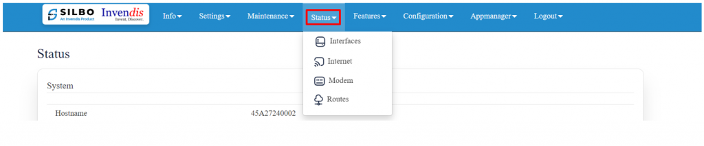 4.1 Interfaces

Each network device (interface) is associated with specific traffic statistics, uptime, and status. Active interfaces are operational, while inactive interfaces are not currently transmitting data.

Looking on the network status the user can check if the cellular, wifi, ewan, vpn etc is up.
4.2 Internet
In this submodule the user can view the status of the internet connections.
To see the latest status of the internet connection the user needs to click on the refresh button.
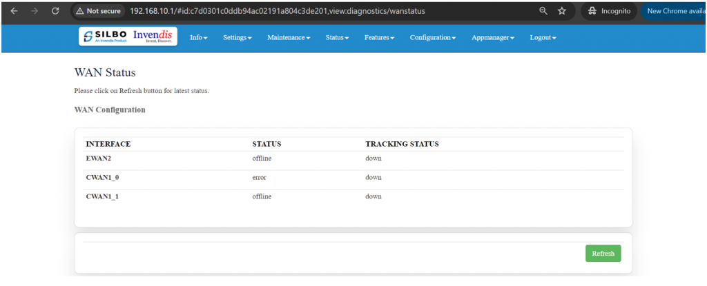 4.3 Modem

This modem status page provides comprehensive information about the cellular connection's network operator, technology, mode, and various signal quality metrics.

4.4 Routes
This configuration shows how the router directs traffic between different networks and interfaces, ensuring proper communication within the local network and to external networks via the default gateway.
ARP Table: Maps IP addresses to MAC addresses for devices on the network, helping in identifying which device is on which interface.
IPv4 Routes: This shows which network is directly connected on which interface.
Example: Network 192.168.10.0/24 is directly connected on interface eth0.1.
IPv6 Routes: Similar routes as IPv4, but this time listed under IPv6 routing rules.
Example: Local networks 192.168.10.0/24 and 192.168.100.0/24 are managed through eth0.1 and ra0, respectively.
*Refer the below image*

5. Features
In this module the user can see all the features that the router device has.
This module includes 7 features.
- Mac Address Binding
- URL Filtering
- Web Server
- Wi-Fi MacID Filtering
- Routing
- DMZ
- Others

5.1 Mac Address Binding
MAC address binding is a configuration that binds a specific MAC address to a specific IP address. This ensures that a particular device on the network always receives the same IP address from the DHCP server, which can be useful for network management, security, and ensuring consistent network behaviour.
Under this submodule the user can configure/update/edit the IP Address for MAC.
You can edit the pre-existing configuration, or you can ‘Add’ in the ‘New MAC ADDRESS’ field.

EDIT:

Specification details are given below:
| SN | Field Name | Sample Value | Description |
| 1 | Device Name | Macbinding1 | A user-defined name for the binding configuration. |
| 2 | MAC Address | 48:9e:bd:da:45:91 | The unique identifier for the network interface of the device to which the IP address will be bound. |
| 3 | IP Address | 192.168.10.55 | The IP address that will be consistently assigned to the device with the specified MAC address. |
By applying this configuration, the DHCP server will always assign the IP address 192.168.10.55 to the device with the MAC address 48:9e:bd:da:45:91, ensuring consistency and stability in network addressing for that device.
- Once the user modifies the MAC address /IP Address then click on the save button to save the changes done.
- The user can click on the deleted button to delete an existing configured device.
Post all the changes the user needs to click on the update to reflect all the changes in the application.
5.2 URL Filtering
In this submodule the user should provide the URL which needs to be blocked for the device. By implementing URL filtering with the specified URL, you can control and restrict access to certain websites, thereby improving network security and managing user access.

To add the new URL for blocking, click on the Add New button.
Once the user clicks on the Add New button a new pop will appear in that page write the URL and click on the save.
The user can select the status of that URL while defining the URL.

To edit / delete the existing URL the user needs to click on the edit /deleted button respectively.

Click on “save” after the changes are done as per the need.
5.3 Web Server
This configuration will allow your device to serve web traffic securely over HTTPS, keep its system time synchronized, and ensure that all HTTP traffic is redirected to HTTPS for better security.

EDIT:

Specification details are given below:
| SN | Field Name | Sample Value | Description |
| 1 | Enable HTTP | HTTP Port: 80
Enable or disable the HTTP server. |
Port 80 is the default port for HTTP traffic. It is used to serve web pages over an unencrypted connection. |
| 2 | Enable HTTPS | HTTPS Port: 443
Enable or disable the HTTPS server. |
Port 443 is the default port for HTTPS traffic. It is used to serve web pages over an encrypted connection. |
| 3 | Redirect HTTPS | Option to redirect HTTP traffic to HTTPS. | When enabled, all HTTP requests will be automatically redirected to the HTTPS port to ensure secure communication. |
| 4 | Session Timeout (in millisecs) | Ex: 60000 | In this scenario the webpage will logout after 60secs of inactivity. |
| 5 | RFC1918 Filter | Enable/Disable | When enabled, this filter can block traffic from private IP ranges (e.g., 192.168.x.x, 10.x.x.x) from being routed through the public internet, enhancing network security. |
| 6 | Enable NTP Sync | Enable or disable NTP synchronization. | Synchronizes the device’s system clock with an external NTP server to maintain accurate time. |
| 7 | NTP Server | 0.openwrt.pool.ntp.org | The address of the NTP server used for time synchronization. The openwrt.pool.ntp.org server is a public NTP server pool. |
| 8 | NTP Sync Interval (In Minutes) | 15 | The interval at which the device will sync its clock with the NTP server, set to every 15 minutes in this case. |
Click on save once changes are made.
5.4 Wi-Fi MacID Filtering
Wireless MAC ID Filtering allows you to control which devices can connect to your wireless network based on their MAC (Media Access Control) addresses. This can help enhance security by allowing only specified devices to access the network.
It is further divided into 2 categories,
WIFI 2.4G AP
WIFI 2.4G AP Guest

Before adding the MacIDs the user needs to select the mode from the dropdown menu.
In ‘Change Mode’ select one option,
Blacklist
In blacklist mode, you specify which MAC addresses are not allowed to connect to the wireless network. Devices not on the blacklist will be able to connect.
Whitelist
In whitelist mode, you specify which MAC addresses are allowed to connect to the wireless network. Devices not on the whitelist will be blocked.
To Add the MacID the user needs to click on Add New option.
 Specification details are given below:
| SN | Field Name | Sample Value | Description |
| 1 | Status | Enable/Disable | Enable or disable the MAC ID filtering. |
| 2 | MAC ID | Example: e8:6f:38:1a:f2:61 | The MAC address of the device to be whitelisted or blocklisted. |
| 3 | Network Name | Example: WIFI 2.4G AP or Wi-Fi 2.4G AP Guest. | The network to apply the MAC ID filtering. |
Once the required MAC ID and Network Name is configured the user needs to click on the save button to add the details.
The user needs to click on the edit button to do modifications on the pre-existing configuration.
Once the required MACID / Network Name is modified the user needs to click on the save button to reflect the changed value in the application.
5.5 Routing
In this submodule the user can configure the parameters related to routing of the device like Target address, Networks address etc. Routing configurations allow network packets to be directed between different subnets and networks.
It is further divided into 2 sections,
Static IPV4 Routes
Advanced Static IPV4 Routes
Static IPV4 Routes:
Click on ‘Add’ to add a new interface.

EDIT:
To edit the existing device the user needs to click on the edit option.
Once the changes are done click on the save button to save all the changes.
Click on the deleted button to delete the existing device detail.

Specification details are given below:
| SN | Field Name | Sample Value | Description |
| 1 | Interface | Ex: eth0.1 | The network interface to be used for this route. Select the one to use from dropdown. |
| 2 | Target | Ex: 192.168.20.0 | The destination subnet to which traffic should be routed. |
| 3 | IPv4 Netmask | 255.255.255.0 | The subnet mask for the target network. |
| 4 | Metric | 0 | The priority of the route.
Lower values indicate higher priority. |
| 5 | IPv4 Gateway | Ex: 192.168.10.1 | The gateway IP address to be used for routing traffic to the target subnet. |
| 6 | Route Type | Unicast | Standard route for individual destination IP addresses.
Custom changes can be made. |
Click on save once configuration changes have been made.
Advanced Static IPV4 Routes:
Click on ‘Add’ to add a new interface.

EDIT:
To edit the existing device the user needs to click on the edit option.
Once the changes are done click on the save button to save all the changes.
Click on the deleted button to delete the existing device detail.

Specification details are given below:
| SN | Field Name | Sample Value | Description |
| 1 | Interface | Ex: ra0 | The network interface through which the traffic will be routed. Select as per requirement. |
| 2 | To | Ex: 192.168.10.1 | This is the target address to which the traffic is being directed. In this case, all traffic destined for 192.168.10.1 will follow this route. |
| 3 | IPv4 Netmask | 255.255.255.192 | This defines the subnet of the destination address. |
| 4 | Table | 1.) Local
2.) Main 3.) Default 4.) 220 5.) custom |
1.) This table contains local routes for the addresses assigned to the local interfaces. It's typically used for host and broadcast addresses.
2.) The primary routing table used by the system. 3.) A fallback table used when no other table is specified. 4.) Often used for policy-based routing. 5.) A user-defined routing table. |
| 5 | From | Ex: 192.168.100.1 | This source address restricts the route to traffic originating from 192.168.100.1. Traffic from other sources won't use this route. |
| 6 | Priority | 20 | The priority value determines the preference of this route. A lower number means higher priority; 20 is relatively high, so this route will be preferred over routes with higher priority values. |
Once all the configurations are done click on the update button to reflect the changes made.
5.6 DMZ
A DMZ (Demilitarized Zone) is a subnetwork that provides an extra layer of security for an organization's internal network.
In this case we are configuring several services (HTTP, HTTPS, SSH, FTP, DNS) in a DMZ, and each service requires the correct internal port (the port used within the network) and external port (the port used by external clients to access the service) settings.

Specification details are given below:
| SN | Field Name | Sample Value | Description |
| 1 | Enable DMZ | Enable/Disable | Enable DMZ to configure it further. |
| 2 | Host IP Address | Ex: 192.168.10.1 | This is the internal IP address of the device or server that will be in the DMZ. |
| 3 | Protocol | 1.) TCP
2.) UDP 3.) ICMP 4.) All |
TCP: Used for reliable services like HTTP, HTTPS, FTP, and SSH.
UDP: Often used for services like DNS that don't require as much reliability. ICMP: Used for sending control messages like "ping." All: Select this if you're unsure which protocol to allow, but it's less secure. |
| 4 | Allow HTTP | Internal Port: 80
External Port: 80 |
Enables web traffic over the unsecured HTTP protocol.
(Port 80 is the standard port for HTTP traffic on our internal network). |
| 5 | Allow HTTPS | Internal Port: 443
External Port: 443 |
Enables secure web traffic over HTTPS. (Port 443 is the standard port for HTTPS on our internal network). |
| 6 | Allow SSH | Internal Port: 52434
External Port: 52434 |
This is a custom port we’re using for SSH.
The default is 22. |
| 7 | Allow FTP | Internal Port: 21/20
External Port: 21/20 |
FTP is used to transfer files between computers.
(These are the standard ports for FTP traffic. Port 21 is used for control commands, and port 20 for the data transfer.) |
| 8 | Allow DNS | Internal Port: 53
External Port: 53 |
Standard DNS port within our internal network. |
5.7 Others
In this page the user will get to do all the other miscellaneous configuration with respect to the device based on the required parameters. Each utility serves a specific purpose, providing various functionalities for managing and troubleshooting network configurations and statuses.

Specification details are given below:
| SN | Field Name | Sample Value | Description |
| 1 | Set Date | Date and time fields (day, month, year, hour, minute, second) | Sets the system date and time to the specified values. |
| 2 | Get Date | System | Retrieves and displays the current system date and time. |
| 3 | ipsec status all | Command ‘Get’ | Displays the status of all IPsec connections. |
| 4 | Wi-Fi Scan | Command ‘Get’ | Initiates a scan for available Wi-Fi networks. |
| 5 | iPerf3 Client | IP address (e.g., 192.168.10.100) | Runs an iPerf3 client to measure network performance. |
| 6 | iPerf3 Server | Command ‘Run’ | Runs an iPerf3 server to measure network performance. |
| 7 | Ping | IP address or domain (e.g., 8.8.8.8) | Sends ICMP echo requests to the specified address to check connectivity. |
| 8 | traceroute | IP address or domain (e.g., 8.8.8.8) | Traces the route packets take to reach the specified address. |
| 9 | NTP Sync | Command ‘Sync’ | Synchronizes the system time with the configured NTP server. |
| 10 | Download Files | File or database identifier | Initiates a download of the specified file or database. |
| 11 | Restart Power | Command ‘Restart’ | Restarts the power of the device. |
| 12 | Restart Modem | Command ‘Restart’ | Restarts the modem. |
| 13 | Run AT Command | Enter AT command | Executes the specified AT command on the modem. |
| 14 | Show Board Configuration | Command ‘Show’ | Displays the current board configuration. |
| 15 | Show VPN Certificate Name | Command ‘Show’ | Displays the name of the VPN certificate in use. |
| 16 | Switch SIM to Secondary (Takes >2 mins) | Command ‘Run’ | Switches the active SIM to the secondary SIM card. |
| 17 | Send test SMS | Phone number (e.g., +911234567890) message text (e.g., "Hello how are you?") | Sends a test SMS to the specified phone number. |
| 18 | ReadlatestSMS | Command ‘Read’ | Reads the most recent SMS received by the device. |
| 19 | Data Usage | From: Start date (YYYY-MM-DD)
To: End date (YYYY-MM-DD) |
Displays data usage statistics for the specified date range. |
| 20 | Monthly Data Usage | Month: Month (e.g., 07)
Year: Year (e.g., 2024) |
Displays data usage statistics for the specified month and year. |
| 21 | Modem Debug Info | Command ‘Read’ | Displays debug information for the modem. |
| 22 | Scan Network operators (Takes >3 mins) | Command ‘Scan’ | Initiates a scan for available network operators. |
| 23 | Network operator list (First Perform Scan Network Operators) | Command ‘Show’ | Displays the list of network operators detected in the previous scan. |
| 24 | ReadLogFiles | Log file identifier | Reads and displays the specified log file |
| 25 | Enable ssh (Admin) | Command ‘Run’ | Enables SSH access for the admin user. |
| 26 | Disable ssh (Admin) | Command ‘Run’ | Disables SSH access for the admin user. |
| 27 | ClearSIM1Data | Command ‘Clear’ | Clears data usage statistics for SIM1. |
| 28 | ClearSIM2Data | Command ‘Clear’ | Clears data usage statistics for SIM2. |
| 29 | Create Bridge with SW_LAN | Network interface identifier | Creates a network bridge with the specified interface and SW_LAN. |
| 30 | Show Bridge | Command ‘Show’ | Displays information about the current network bridges. |
| 31 | Delete Bridge | Command ‘Delete’ | Deletes the specified network bridge. |
| 32 | Output | Any value | Displays output for all the above actions. |
5.8 SNMP Agent Configuration
The SNMP (Simple Network Management Protocol) Agent Configuration is essential for monitoring and managing network devices, such as routers, from a central management system.

Specification details are given below:
| SN | Field Name | Sample Value | Description |
| 1 | Enable SNMP Service | Enable/Disable | Enable this if you want the device to be accessible for SNMP-based monitoring and management. |
| 2 | IP Family | IPV4 | Specifies that SNMP service will operate over IPv4. |
| 3 | Port | 161 | 161 is the default and should be used unless there is a specific need to use a different port. |
| 4 | System OID | 1.3.6.1.4.1.38151 | This unique identifier represents the device in the SNMP management system. |
| 5 | Name | Invendis Router | The name used to identify the device in the SNMP management system. |
| 6 | Contact | Invendis@invendis.co | The email address of the person responsible for the device, used for administrative contact. |
| 7 | Location | Bangalore | The physical location of the device. |
| 8 | SNMP Version | Version-1,
Version-2, Version-3 |
Version-1: Basic and outdated, offering no security.
Version-2: An improvement over Version-1 with better performance and some security features. Version-3: The most secure, offering authentication and encryption (AuthPriv). |
| 9 | Security (for SNMP Version-3) | NoAuthNoPriv
AuthNoPriv AuthPriv |
No Authentication, No Privacy
Authentication, No Privacy Authentication and Privacy |
| 10 | Username | Ex: admin | The username used for SNMP authentication. |
| 11 | Authentication Password | ******* | This password is used to authenticate the SNMP user. |
| 12 | Privacy Password | ******* | This password is used to encrypt SNMP messages. |
| 13 | Download MIB File | Download | Click this to download the MIB file associated with the device’s SNMP configuration. |
Click on save tab to save changes.
5.9 Connection Diagnostics
This can ensure that your connection diagnostics application effectively monitors and reports the status of your network connections, providing valuable data for troubleshooting and performance optimization.

This Application works in 3 parts,
1.) General settings
2.) Connection status and management
3.) Application Start/Stop
 General settings:
First make configuration changes in this section and save.

Specification details are given below:
| SN | Field Name | Sample Value | Description |
| 1 | Enable Connection Diagnostics | Enable/Disable | This option enables or disables the connection diagnostics functionality. |
| 2 | Check Interval (in seconds) | Value: 120 | Specifies how often (in seconds) the diagnostics checks are performed. In this case, every 120 seconds. (min 60 secs) |
| 3 | Number of Pings | Value: 5 | Determines ping requests sent during each check. |
| 4 | Ping Packet Size (in Bytes) | Value: 56 | Defines the size of each ping packet in bytes. |
| 5 | Send to remote MQTT Broker | Enable/Disable | This option enables the sending of diagnostic data to a remote MQTT broker. |
| 6 | Publish Data Format | CSV / JSON | Specifies the format in which the diagnostic data will be published to the MQTT broker. You can choose either CSV (Comma-Separated Values) or JSON (JavaScript Object Notation). |
| 7 | MQTT Broker url | Value: broker.hivemq.com | The URL of the MQTT broker where the diagnostic data will be sent. |
| 8 | TCP port | Value: 1883 | The TCP port used to connect to the MQTT broker. Port 1883 is the default port for MQTT. |
| 9 | Topic | Value: 37A26230014/connectionDiagnostics | The MQTT topic under which the diagnostic data will be published. This topic is used to categorize and identify the data. |
Connection status and management:
To setup a connection,
Click on ‘Add new target’
Enter Target IP (Ex: 8.8.8.8)
Click ‘Add’
Target has been added successfully.

Application Start/Stop:
To check whether the target Ip is sending and receiving packets, you need to start the application to see the desired output.

As shown above, our target Ip is sending packets successfully.
You can Add as many target IP’s you need to monitor.
You can leave the application on for monitoring else ‘Stop’ the application.
5.10 Package Manager
A Package Manager is a tool or interface used to manage software packages (applications, libraries, tools) on a system.
The package manager interface you are looking at likely allows you to manage the software installed on your device, such as networking tools, firmware, or other applications relevant to your system.
This section has 3 sub-sections,
Installed APP
Available APP
Manual Upgrade

Installed APP:
When you select Installed APP, you will see all the software that is actively running or installed on the device.
This could include system utilities, network management tools, monitoring software, or any third-party apps that were previously installed.
Common Actions:
- View Details: You can check each application's version, source, and installation date.
- Uninstall: You can remove applications that are no longer needed.
- Check for Updates: You can see if there are updates available for any installed application.
Available APP:
When you select Available APP, you will see a list of software that can be installed from the system's repositories or sources.
These applications are not yet installed but are ready for installation if needed.
Common Actions:
- Install: You can install any of the available applications by selecting them.
- View Details: You can review each application's description, version, and functionality before installing.
- Search: You can search for specific apps by name or category.
Manual Upgrade:
In contrast to automatic updates, Manual Upgrade lets you take control over which packages or applications you want to upgrade and when.
This can be useful if you need to avoid upgrading certain apps due to compatibility or testing purposes, or if you want to perform updates at a specific time.
Common Actions:
- Check for Updates: The system will check for available updates for installed apps.
- Select Updates: You can select which packages to update manually.
- Upgrade Now: You can start the upgrade process immediately for selected apps.
6.Configuration
These are gateway features that can be configured as per requirements.
It is divided into 5 sections,
1.) Source Configuration
2.) Send Configuration
3.) Port Configuration
4.) Cloud Configuration
5.) Modbus Configuration

6.1 Source Configuration
These configurations ensure that the system regularly acquires data from various interfaces at specified intervals, allowing for efficient monitoring and management of connected devices and sensors.
 Specification details are given below:
| SN | Field Name | Sample Value | Description |
| 1 | Enable RS485Line1 | Enable/Disable | This option enables the RS485 Line 1 interface for energy meter readings. |
| 2 | Overall Periodicity of RS485 Line 1 Energy meter Readings (In Seconds >= 60) | Value: 120 | Defines the interval in seconds at which readings are taken from the RS485 Line 1 energy meter. The minimum allowable interval is 60 seconds. |
| 3 | Delay between each Energy meter Readings (in Milliseconds) | Value: 2000 | Specifies the delay in milliseconds between individual readings from the energy meter on RS485 Line 1. |
Click on save once changes have been made.
6.2 Send Configuration
Send configuration allows to choose type of string that should be sent to a cloud platform.
SILBO devices do offer 3 different options as shown below.
CSV (CSV allows fixed CSV)
Fixed JSON
Editable JSON. (JSON option is the editable JSON option)

Data sender Configuration is divided into major 2 parts,
JSON
CSV
JSON is further divided into 1 category,
Modbus Sender:

Select the field input you wish to add from the ‘Field Content tab’.
Give a desired JSON Key Name you wish to publish in the ‘Field JSON Key Name’ tab.
Once configured, click on Add.
JSON option allows editable JSON in which we can change which parameters should be sent and what name we should use to the tag.

What changes we can do in JSON edit to the above list.
Let’s change slave_id to some other name as “Slave number”.

Even custom fields can be added, for example if location name should be sent by router/gateway in JSON packet then it can be configured as shown.

CSV:
This option sends data packets in CSV (Comma-Separated Values) format.

Specification details are given below:
| SN | Field Name | Sample Value | Description |
| 1 | Device ID | GRD44B-5R | A unique identifier for the device. |
| 2 | Record Start Mark | [ | This character marks the beginning of a data record. It's used to indicate where a new data record starts in the transmitted packet. |
| 3 | Record End Mark | ] | This character marks the end of a data record. It signals the end of the data for one record before a new one starts. |
| 4 | Register Start Mark | < | This character marks the beginning of a register within a data record. A register typically represents an individual data field within the record. |
| 5 | Register End Mark | > | This character marks the end of a register within a data record. It indicates where the data for a particular field end. |
| 6 | Invalid Data Character | N | Used to indicate that the data for a particular register is invalid or could not be collected. This helps in identifying which data points are not usable. |
| 7 | Failure Data Character | NA | Used to indicate that there was a failure in collecting or processing the data for a particular register. It signifies that an error occurred, and the data point could not be obtained. |
Click on save once changes are made.
6.3 Port Configuration
Serial port configuration involves setting parameters for serial communication, allowing data exchange between devices via serial ports.
Port Configuration is divided into 4 port mode,
Transparent Serial to Remote TCP Client
Transparent Serial to Remote TCP Server
Modbus TCP Master to Modbus RTU Slave
Modbus RTU Master to Modbus TCP Slave
 Transparent Serial to Remote TCP Client:
![]()
Specification details are given below:
| SN | Field Name | Sample Value | Description |
| 1 | Port Mode | Transparent Serial to Remote TCP Client | Configures the serial port to send data directly to a remote TCP client without any additional protocol layers, making it "transparent." |
| 2 | Transparent Serial Port Mode | 1.) raw
2.) rawlp 3.) telnet 4.) off |
1.) It's a straightforward data transfer where the serial data is sent as-is.
2.) "Rawlp" stands for "raw with local processing". Typically, it involves some minimal local processing before transmission. 3.) This allows the serial connection to be accessed and managed over a Telnet session. 4.) The "off" mode disables the transparent serial port functionality. |
| 3 | Time Out | no time out | Ensures that the serial port does not time out, meaning it will continuously wait for data without closing the connection due to inactivity. |
| 4 | Local Listener TCP Port | 3040 | Sets the TCP port number to 3040 for the local listener to accept incoming TCP connections. |
| 5 | Baud Rate | 9600 | This is a common baud rate for serial communication, balancing speed and reliability. |
| 6 | No Of Stopbits | 1 | Configures the serial communication to use 1 stop bit, which is a common setting ensuring the end of each byte is clearly marked. |
| 7 | No Of Databits | 8 | Sets the number of bits in each transmitted byte to 8. |
| 8 | Parity | 1.) None
2.) Even 3.) Odd 4.) Space 5.) Mark |
1.) No parity bit is added to the data byte.
2.) Ensures that the total number of 1-bits in the data byte plus the parity bit is even. 3.) Ensures that the total number of 1-bits in the data byte plus the parity bit is odd. 4.) The parity bit is always set to 0, regardless of the data. 5.) The parity bit is always set to 1, regardless of the data. |
| 9 | Flow Control | 1.) RTSCTS
2.) NONE 3.) DTRDSR 4.) XONXOFF |
1.) Request to Send / Clear to Send
2.) No flow control is used. 3.) Data Terminal Ready / Data Set Ready 4.) Software flow control using specific control characters (XON and XOFF) to manage data flow. |
| 10 | Read Trace | Enable/Disable | Enables logging of data being read from the serial port. |
| 11 | Write Trace | Enable/Disable | Enables logging of data being written to the serial port. |
Click on save once configuration changes are made.
Transparent Serial to Remote TCP Server:
Configures the port to act as a bridge, converting serial data into TCP packets sent to a remote TCP server.
![]()
Specification details are given below:
| SN | Field Name | Sample Value | Description |
| 1 | Port Mode | Transparent Serial to Remote TCP Server | Defines how the serial port will operate in relation to the remote server. |
| 2 | Remote Server IP | Ex: 192.168.10.1 | Field must not be empty: This is a required field, and you must provide a valid IP address for proper communication. |
| 3 | Remote Server Port | Ex: 1883 | Field must not be empty: This is a required field, and you must specify the correct port number used by the server. |
| 4 | Transparent Serial Port Mode | 1.) raw
2.) rawlp 3.) telnet 4.) off |
1.) It's a straightforward data transfer where the serial data is sent as-is.
2.) "Rawlp" stands for "raw with local processing". Typically, it involves some minimal local processing before transmission. 3.) This allows the serial connection to be accessed and managed over a Telnet session. 4.) The "off" mode disables the transparent serial port functionality. |
| 5 | Time Out | no time out | Ensures that the serial port does not time out, meaning it will continuously wait for data without closing the connection due to inactivity. |
| 6 | Local Listener Interface IP Address | Field must not be empty: This is a required field for specifying which local IP address will be used for listening. | |
| 7 | Local Listener TCP Port | 3040 | The TCP port number on the local device that will be used to listen for incoming data. |
| 8 | Baud Rate | 9600 | Standard baud rate, common for many serial devices. |
| 9 | No Of Stopbits | 1 | Indicates that one stop bit is used, which is standard for most serial communications. |
| 10 | No Of Databits | 8 | Indicates that 8 data bits are used per byte, which is a common setting. |
| 11 | Parity | 1.) None
2.) Even 3.) Odd 4.) Space 5.) Mark |
1.) No parity bit is added to the data byte.
2.) Ensures that the total number of 1-bits in the data byte plus the parity bit is even. 3.) Ensures that the total number of 1-bits in the data byte plus the parity bit is odd. 4.) The parity bit is always set to 0, regardless of the data. 5.) The parity bit is always set to 1, regardless of the data. |
| 12 | Flow Control | 1.) RTSCTS
2.) NONE 3.) DTRDSR 4.) XONXOFF |
1.) Request to Send / Clear to Send
2.) No flow control is used. 3.) Data Terminal Ready / Data Set Ready 4.) Software flow control using specific control characters (XON and XOFF) to manage data flow. |
| 13 | Read Trace | Enable/Disable | Option to enable tracing of incoming data from the serial port, useful for debugging. |
| 14 | Write Trace | Enable/Disable | Option to enable tracing of outgoing data from the serial port, useful for debugging. |
Click on save once configuration changes are made.
Modbus TCP Master to Modbus RTU Slave:
Configures the serial port to function as a Modbus TCP Master that communicates with a Modbus RTU Slave over the serial connection.
This setup is used to send Modbus TCP commands to a Modbus RTU device via a serial-to-TCP gateway.

Specification details are given below:
| SN | Field Name | Sample Value | Description |
| 1 | Port Mode | Modbus TCP Master to Modbus RTU Slave | This setup is used to send Modbus TCP commands to a Modbus RTU device via a serial-to-TCP gateway. |
| 2 | Baud Rate | 9600 | The speed at which data is transmitted over the serial connection. |
| 3 | Parity | 1.) None
2.) Even 3.) Odd |
1.) No parity bit is used, meaning no additional error-checking bits are included.
2.) Ensures that the total number of 1-bits in the data byte plus the parity bit is even. 3.) Ensures that the total number of 1-bits in the data byte plus the parity bit is odd. |
| 4 | No of Stopbits | 1 | Indicates that one stop bit is used, which is standard for most serial communications. |
| 5 | No of Databits | 8 | Indicates that 8 data bits are used per byte, which is a common setting. |
| 6 | Local Listener Interface IP Address | Field must not be empty: You need to provide a valid IP address where the TCP connections will be received. | |
| 7 | TCP Port | 502 | This is the standard port for Modbus TCP communication. |
| 8 | Max. Number of Retries | 5 | The maximum number of times to retry sending a request if the initial attempt fails. |
| 9 | Delay Between Each Request (In milliseconds) | 500 | The delay between consecutive Modbus requests to avoid overwhelming the system or device. |
| 10 | Response Wait Time (In milliseconds) | 500 | The maximum time to wait for a response from the Modbus RTU Slave before considering the request failed. |
| 11 | Connection Timeout (In seconds) | 0 | A value of 0 typically means no timeout is set, so the system will wait indefinitely. |
| 12 | Inactivity Timeout (In seconds) | The time to wait before closing a connection if no activity is detected. |
Click on save once configuration changes have been made.
Modbus RTU Master to Modbus TCP Slave:
Configures the serial port to function as a Modbus RTU Master that communicates with a Modbus TCP Slave over a network. This setup is used to send Modbus RTU commands from a master device to a Modbus TCP device via a TCP-to-serial gateway.

Specification details are given below:
| SN | Field Name | Sample Value | Description |
| 1 | Port Mode | Modbus RTU Master to Modbus TCP Slave | This setup is used to send Modbus RTU commands from a master device to a Modbus TCP device via a TCP-to-serial gateway. |
| 2 | Baud Rate | 9600 | The speed at which data is transmitted over the serial connection. |
| 3 | Parity | 1.) None
2.) Even 3.) Odd |
1.) No parity bit is used, meaning no additional error-checking bits are included.
2.) Ensures that the total number of 1-bits in the data byte plus the parity bit is even. 3.) Ensures that the total number of 1-bits in the data byte plus the parity bit is odd. |
| 4 | No of Stopbits | 1 | Indicates that one stop bit is used, which is standard for most serial communications. |
| 5 | No of Databits | 8 | Indicates that 8 data bits are used per byte, which is a common setting. |
| 6 | TCP Slave Address | Field must not be empty | The IP address of the Modbus TCP Slave device to which the master will send requests. |
| 7 | TCP Slave Port | Field must not be empty | The port number on the Modbus TCP Slave device for receiving Modbus requests. |
| 8 | Max. Number of Retries | 5 | The maximum number of times to retry sending a request if the initial attempt fails. |
| 9 | Delay Between Each Request (In milliseconds) | Field must not be empty | The delay between consecutive Modbus requests to avoid overwhelming the system. |
| 10 | Response Wait Time (In milliseconds) | 500 | The maximum time to wait for a response from the Modbus TCP Slave before considering the request failed. |
| 11 | Connection Timeout (In seconds) | 0 | A value of 0 typically means no timeout is set, so the system will wait indefinitely. |
| 12 | Inactivity Timeout (In seconds) | Field must not be empty | The time to wait before closing a connection if no activity is detected. |
Click on save once configuration changes have been made.
6.4 Cloud Configuration
In this section you can select the protocol by which you need to send data to cloud.
There are 3 Cloud/Protocol available,
HTTP
MQTT
Azure
 HTTP Cloud/Protocol:
This configuration sets up communication between your device and cloud service using the HTTP cloud.
 Specification details are given below:
| SN | Field Name | Sample Value | Description |
| 1 | Site ID | Ex: ‘Site123’ or ‘Device456’. | A unique identifier for your site or device within the cloud service. |
| 2 | Cloud / Protocol | HTTP | The protocol used for communication with the cloud service. |
| 3 | HTTP URL | Example: www.httpbin.org/post | The endpoint URL of the cloud service where data will be sent. |
| 4 | HTTP Port (Optional) | Leave it blank for the default port. | The port number for the HTTP connection. This is optional because the default port for HTTP (80) is used if not specified. |
| 5 | Enable Authentication | Enable/Disable | Enable this if your cloud service requires a username and password. |
| 6 | Username | Example: admin | The username for authentication with the cloud service. |
| 7 | Password | ***** | The password for authentication with the cloud service. |
| 8 | Enable Server Response Validation | Enable/Disable | Enable this if you need to verify that the server's response is valid. |
| 9 | Server Response | Ex: RecordID or custom | A unique identifier for the record being sent to the cloud service. |
| 10 | Method | 1.) Post
2.) Get |
1.) The HTTP method used for sending data to the cloud service.
2.) The HTTP method used for requesting data from the cloud service. |
MQTT Cloud/Protocol:
This configuration sets up communication between your device and a cloud service using the MQTT protocol.
 Specification details are given below:
| SN | Field Name | Sample Value | Description |
| 1 | Site ID | Example: ‘Site123’ or ‘Device456’. | A unique identifier for your site or device within the cloud service. |
| 2 | Cloud / Protocol | MQTT | The protocol used for communication with the cloud service. |
| 3 | MQTT Host | Example: broker.hivemq.com | The MQTT broker's address (hostname or IP address) that the device will connect to for sending and receiving messages. |
| 4 | MQTT Port | Example: 1883 | This is the default port for unencrypted MQTT connections. |
| 5 | Authentication Mode | 1.) No Authentication
2.) Username/Password 3.) TLS |
1.) Connect to the broker without any credentials.
2.) The Username/Password for authentication with the cloud service. 3.) Upload TLS certificates only if TLS authentication is selected as shown in the above image. |
| 6 | Enable Publish Over LAN | Enable/Disable | When enabled, the device will also publish MQTT messages over the local area network (LAN). |
| 7 | RS485 Topic (Optional) | Example: RS485Data1 | The MQTT topic for publishing RS485 data. |
| 8 | Command Request Topic (Optional) | Example: CommandRequest1 | The topic to which the device listens for command requests. Leave it blank if not in use. |
| 9 | Command Response Topic (Optional) | Example: CommandResponse1 | The topic on which the device publishes responses to commands. Leave it blank if not in use. |
Click on save once configuration changes have been made.
Azure:
This configuration sets up the connection to Azure IoT Hub using either MQTT or HTTP protocols with a specified connection string.
 Specification details are given below:
| SN | Field Name | Sample Value | Description |
| 1 | Site ID | Example: ‘Site123’ or ‘Device456’. | A unique identifier for your site or device within the cloud service. |
| 2 | Cloud / Protocol | Azure | The cloud service and protocol used for communication. |
| 3 | Protocol | 1.) MQTT
2.) HTTP |
1.) A lightweight messaging protocol suitable for IoT devices.
2.) A protocol used for communication over the web, commonly used for RESTful services. |
| 4 | Connection String | e.g., invendis-iot-hub.azure-devices.net. | The primary or secondary key used to authenticate the device with the IoT Hub. |
Click on save once configuration changes have been made.
6.5 Modbus Configuration
Modbus Configuration involves setting up communication parameters for Modbus devices, including baud rate, parity, stop bits, data bits, TCP/RTU settings, and timeout/retry settings for reliable data exchange.
Click on “Add Device” to start a new configuration.
This Configuration has 4 sections,
1.) Parameter Configuration
2.) Block Config
3.) Register Config
4.) Alarm/Event Config

Parameter Configuration:
As shown in the image below, there are two types of protocol used in Modbus configuration.
1.) RTU (Remote Terminal Unit)
2.) TCP (Transmission Control Protocol)
Details of both protocols is mentioned in the specification table.
Modbus Protocol: RTU

Specification details are given below:
| Modbus protocol: RTU | |||
| 1 | DEVICE NAME | Ex: Invendis | This is the name assigned to the Modbus device for identification purposes. |
| 2 | Baud rate | 300 | 1200 | 1800 | 2400 | 4800 | 19200 | 38400 | default: 9600 | The baud rate determines the communication speed between devices, measured in bits per second. |
| 3 | Parity | 1.) NONE
2.) ODD 3.) EVEN |
1.) No parity bit is added to the data byte.
2.) Ensures that the total number of 1-bits in the data byte plus the parity bit is even. 3.) Ensures that the total number of 1-bits in the data byte plus the parity bit is odd. |
| 4 | Meter ID | 1 | The Meter ID is a unique identifier for the specific meter within the network. Each Modbus device on the network must have a unique ID to differentiate it from others. |
| 5 | Meter Model | Example: abcd | This field specifies the model of the meter. |
| 6 | Port number | RS485 Port-1 | This specifies which RS485 port on the device is being used for communication. |
| 7 | Slave Address | Example: 1 | The slave address identifies the specific slave device on the Modbus network. Each slave must have a unique address so that the master can communicate with it individually. |
| 8 | No. of Databits | 7/8 | Indicates that 8 data bits are used per byte, which is a common setting. |
| 9 | No. of Stopbits | 1/2 | Configures the serial communication to use 1 stop bit, which is a common setting ensuring the end of each byte is clearly marked. |
Modbus Protocol: TCP

Specification details are given below:
| Modbus protocol: TCP | |||
| 1 | DEVICE NAME | Ex: Invendis | This is the name assigned to the Modbus device for identification purposes. |
| 2 | Modbus Comm IP | Ex: 192.168.10.147 | IP of the device you are communicating with. |
| 3 | Modbus Comm Port | Ex: 502 (default) | Give a specified TCP port number |
| 4 | Modbus Comm Timeout | Ex: 60 | This refers to the maximum amount of time the master device will wait for a response from a slave device before it assumes a communication failure. |
| 5 | Meter ID | 1 | The Meter ID is a unique identifier for the specific meter within the network. Each Modbus device on the network must have a unique ID to differentiate it from others. |
| 6 | Meter Model | Example: abcd | This field specifies the model of the meter. |
| 7 | Slave Address | Example: 1 | The slave address identifies the specific slave device on the Modbus network. Each slave must have a unique address so that the master can communicate with it individually. |
Block Config:

Specification details are given below:
| SN | Field Name | Sample Value | Description |
| 1 | Funtion Code | read coils (1)
read input coils (2) read holding registers (3) read input registers (4) |
The function code indicates the operation to be performed. In Modbus, each operation has a specific function code. |
| 2 | Start Register | Example: 0 | The start register indicates the address of the first register to be read in the slave device. |
| 3 | Register Count | Example: 10 | This specifies the number of consecutive registers to read starting from the start register. |
Click on “Add Block” below to add another set of parameters.
Register Config:
In this section you can add multiple parameters to read in ‘Default Mapping’ & ‘Custom Mapping’ field.
*Refer the image below*

| SN | Field Name | Sample Value | Description |
| 1 | Default mapping | 1.) Tag Name = (Ex: FQ)
2.) Data type = Hexadecimal; Floating point | Floating point (Swapped Byte) | 16bit INT, high byte first | 16bit INT, low byte first | 16bit UINT, high byte first | 16bit UINT, low byte first | 32bit UINT (byte order 1,2,3,4) | 32bit UINT (byte order 4,3,2,1) | 32bit INT (byte order 1,2,3,4) | 32bit INT (byte order 4,3,2,1) |
1.) Input value name.
2.) Defines how read data will be stored. |
| 2 | Custom mapping | 1.) Register name:
2.) Start register: 3.) Register count: 4.) Data type = Hexadecimal; Floating point | Floating point (Swapped Byte) | 16bit INT, high byte first | 16bit INT, low byte first | 16bit UINT, high byte first | 16bit UINT, low byte first | 32bit UINT (byte order 1,2,3,4) | 32bit UINT (byte order 4,3,2,1) | 32bit INT (byte order 1,2,3,4) | 32bit INT (byte order 4,3,2,1); 1 bit |
1.) Input value name.
2.) First register in custom register block. 3.) Path to file in which the custom register block will be stored. 4.) Defines how read data will be stored. |
In Register Config,
Click on ‘Add’ to add new parameters.
Click on ‘Show JSON’ to view an example value of how the data will be presented.
Click on ‘Add Device’ once configuration changes have been made.
Alarm/Event Config:
 Specification details are given below:
| SN | Field Name | Sample Value | Description |
| 1 | Category | 1.) Alarm
2.) Event |
Alarm: Specifies that the configuration is for an alarm, which typically triggers when certain conditions are met.
Event: Specifies that the configuration is for an event, which might log information or trigger actions without necessarily being an alarm. |
| 2 | Status | 1.) Enabled
2.) Disabled |
Enabled: Activates the alarm or event, making it operational.
Disabled: Deactivates the alarm or event, making it non-operational. |
| 3 | Name | Ex: vtg | The name or identifier for the alarm/event. |
| 4 | Function code | read coils (1)
read input coils (2) read holding registers (3) read input registers (4) |
These function codes are typically based on the Modbus protocol, indicating what type of data is being monitored. |
| 5 | Start Register | Ex: 0 | The address of the first register to monitor. |
| 6 | No_of Reg | Ex: 10 | The number of consecutive registers to monitor from the starting register. |
| 7 | Data Type | Hexadecimal; Floating point | Floating point (Swapped Byte) | 16bit INT, high byte first | 16bit INT, low byte first | 16bit UINT, high byte first | 16bit UINT, low byte first | 32bit UINT (byte order 1,2,3,4) | 32bit UINT (byte order 4,3,2,1) | 32bit INT (byte order 1,2,3,4) | 32bit INT (byte order 4,3,2,1); Boolean | Provides options for the type of data being monitored, such as integer, float, Boolean, etc. |
| 8 | Upper Thresh/
Alarm Value |
Ex: 2 | The value at which the alarm is triggered if the monitored parameter exceeds this upper threshold. |
| 9 | Upper Hys | Ex: 2 | This value is subtracted from the upper threshold to set the point at which the alarm resets, preventing rapid toggling. |
| 10 | Lower Thresh | Ex: 2 | The value at which the alarm is triggered if the monitored parameter falls below this lower threshold. |
| 11 | Lower Hys | Ex: 1 | This value is added to the lower threshold to set the point at which the alarm resets, preventing rapid toggling. |
Click on “Add Alarm” to add another Alarm/Event.
Click on ‘Show JSON’ to view an example value of how the data will be presented.
Click on ‘Add Device’ once configuration changes have been made.
7. Appmanager
Appmanager is a system utility that manages the installation, configuration, and execution of software applications on a device.
This section is divided into 6 categories,
- Application Start/Stop
- Application Software Upgrade
- Modbus Utility Configuration
- Import/Export Application Configurations
- App Health Status
- IO Utilities

7.1 Application Start/Stop
All changes made in ‘Configuration’ section should be saved into backend and to do that navigate to Appmanager >> Application Start/Stop.
Click on update to save all the changes made in configuration section.
Once updated click on start.

Make sure application is started to send data to cloud, once started it can be seen start option is replaced by Stop as shown above.
7.2 Application Software Upgrade
In this section you can upgrade software manually or automatically.
For auto upgrade, enable auto upgrade tab,
This is further divided into 2 sections,
Client and server settings
Auto Upgrade Interval

Specification details are given below:
| Client and server settings | |||
| SN | Field Name | Sample Value | Description |
| 1 | Authentication | Enable/Disable | Enable if username/password is required. |
| 2 | Username | XXXX | The username required to authenticate with the server. |
| 3 | Password | XXXX | The password required to authenticate with the server. |
| 4 | Server address | ftp://XXXX | The URL or IP address of the server where the upgrade files are located. |
| 5 | Connection timeout | Ex: 180 | The maximum time (in seconds) the system will wait to establish a connection with the server before timing out. |
| 6 | Operation timeout | Ex: 240 | The maximum time (in seconds) the system will wait for the upgrade operation to complete before timing out. |
| Auto Upgrade Interval | |||
| SN | Field Name | Sample Value | Description |
| 1 | Minutes | Example: 56 | Set the minute part of the interval when the auto-upgrade check will occur |
| 2 | Day Of Month | Example: all | Specifies the days of the month when the auto-upgrade check should occur. |
| 3 | Month | Example: all | Specifies the months during which the auto-upgrade check should occur |
| 4 | Day Of Week | Example: all | Specifies the days of the week when the auto-upgrade check should occur. |
You can also check the current software version and manually upgrade software as shown below.
To Manually upgrade Application,
Enter the correct ‘Checksum’ and ‘Size’ and upgrade the page.
(Please stop the applications before upgrading)

7.3 Modbus Utility Configuration
Any changes to be made in Modbus Configuration to test can be made in Modbus Utility Configuration without disturbing the actual Modbus Configuration.
The working process of ‘Modbus Configuration’ and ‘Modbus Utility Configuration’ are same.
Refer (6.5 Modbus Configuration) for specification details.
 Click on save once configuration changes have been made.
7.4 Import / Export Gateway Configuration
This functionality ensures that you can easily manage, back up, and restore device gateway
configurations, as well as reset the device to default settings when needed.

Export Config:
Usage: Click the "Export Config" button to save the current configuration to a file.
Import Config:
Usage: Click the "Import Config" button and select the text file containing the configuration you want to import.
Reset Config:
Usage: Click the "Reset Config" button to revert the device to its default configuration settings.
7.5 App Health Status
This section provides utilities to check the health and status of various applications and data inputs
within the system. It allows monitoring of the last data produced and sent times for different utilities, as
well as the running status of applications.
*Refer the image below*
 Specification details are given below:
| SN | Field Name | Sample Value | Description |
| 1 | Energymeter Last Data Produced Time | Command ‘Read’ | Displays the last time data was produced by the energymeter. |
| 2 | DIO Last Data Produced Time | Command ‘Read’ | Displays the last time data was produced by the digital input/output system. |
| 3 | Energymeter Last Data Sent Time | Command ‘Read’ | Displays the last time data from the energymeter was sent. |
| 4 | App Running Status | Command ‘Read’ | Displays the current running status of applications. |
| 5 | Download Files | Command ‘Download’ | Choose the desired option from the dropdown menu.
Download data or logs related to the options available. |
| 6 | Output | Display Value | Provides output or feedback based on selected utilities. |
7.6 IO Utilities
This section provides output of various utilities connected to the device.
This section exactly shows whether the connection made is successful or not.
*Refer the image below*
 Specification details are given below:
| SN | Field Name | Sample Value | Description |
| 1 | Modbus Utility | Input: Slave ID | Action: Manage RS485 energy meters by specifying the slave ID. (Read/Write) |
| 2 | Output | Print any values | Action: Will display the results or status messages based on the actions performed using the utilities. |
8.Logout
The user should click on log out option to logged out from the router application.
