RC44 User Manual: Difference between revisions
(Created page with "This page contains the user manual for RB44. Connecting with the device to the System (Laptop/Desktop). To log in to SILBO_RB44 by connecting the router to your laptop or desktop via LAN or using Wi-Fi, please follow the steps below. '''Connecting via LAN:''' Connect your laptop's LAN port to one of the router's LAN interfaces. Ensure that you select any LAN interface (there are two available) while making sure the WAN interface is not used. ...") |
No edit summary |
||
| Line 1: | Line 1: | ||
This page contains the user manual for | This page contains the user manual for RC44. | ||
Connecting with the device to the System (Laptop/Desktop). | Connecting with the device to the System (Laptop/Desktop). | ||
To log in to | To log in to SILBO_RC44 by connecting the router to your laptop or desktop via LAN or using Wi-Fi, please follow the steps below. | ||
| Line 13: | Line 13: | ||
'''How to connect with the | '''How to connect with the SILBO_RC44''' '''application''' | ||
Once the LAN connection is established between the device and the laptop or the desktop | Once the LAN connection is established between the device and the laptop or the desktop | ||
Revision as of 08:43, 26 July 2024
This page contains the user manual for RC44.
Connecting with the device to the System (Laptop/Desktop).
To log in to SILBO_RC44 by connecting the router to your laptop or desktop via LAN or using Wi-Fi, please follow the steps below.
Connecting via LAN:
Connect your laptop's LAN port to one of the router's LAN interfaces. Ensure that you select any LAN interface (there are two available) while making sure the WAN interface is not used.
How to connect with the SILBO_RC44 application
Once the LAN connection is established between the device and the laptop or the desktop
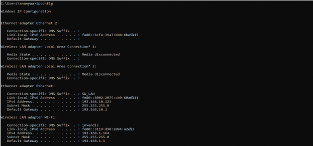
Please open the command prompt and ping go get the ip config of that device.
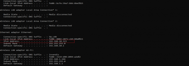
Type the command Ipconfig
It will provide the Ip address/url of that device through which the application can be accessed.
Log In
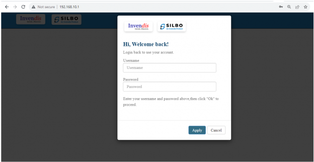
Open the web browser and type the IP address in the URL.
It will show the log in page of the application.
Give the valid credentials for the username and password to login to the application page.
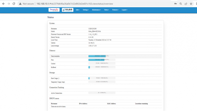
Once the user credentials are provided it will direct to the landing page of the application.
The “Status” landing page shows all the detailed specification of the device like system, memory storage and connection tracking etc.
The application is divided in to 6 Modules.
- Info
- Settings
- Maintenance
- Status
- Features
- Logout
1.Info
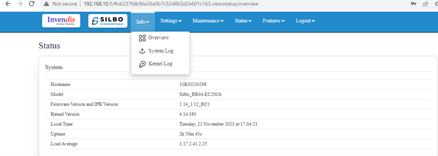
The “Info” module provides the information about the devices to the user.
It provides all the specification related to the hardware, firmware, Networks and the Connection uptimes.
It has 3 submodules.
- Overview
- System Log
- Kernel Log
1.1 Overview
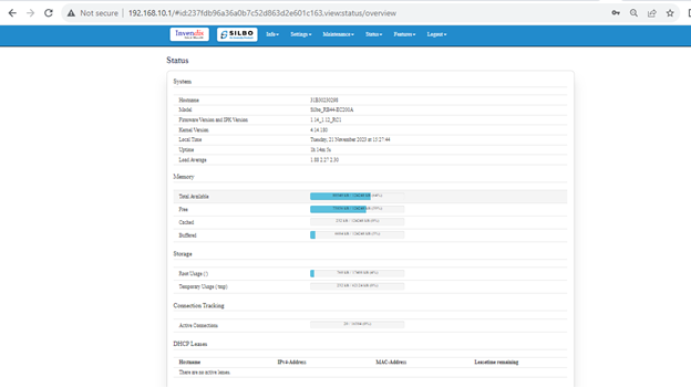
In overview module it displays all the specification categorically of a device like System, Memory, storage, Connection tracking, DHCP Lease.
System
In this section it displays the hardware configured specification of the device.
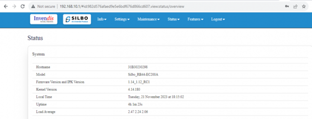
The specifications details are as follows,
| SN | Field name | Sample value | Description |
|---|---|---|---|
| 1 | Hostname | 31B30230298 | This field displays the router serial number of the device |
| 2 | Model | 31B30230298 | This field displays the model number of the device |
| 3 | Firmware Version and IPK Version | 1.14_1.12_RC1 | This field displays the firmware version and IPK version |
| 4 | Kernel Version | 4.14.180 | This field displays the kernel version of the device |
| 5 | Local Time | Tuesday, 21 November 2023 at 18:22:41 | This field displays the local time |
| 6 | Uptime | 4h 9m 19s | This field displays the uptime of the device |
| 7 | Load Average | 2.32 2.14 2.10 | This field displays the average load |
Memory
In this section it displays the memory configured specification of the device.

The specifications details are as follows.
| SN | Field name | Sample value | Description |
| 1 | Total Available | 77928 kB / 124248 kB (62%) | This field displays the total availability of memory space in the device |
| 2 | Free | 72436 kB / 124248 kB (58%) | This field displays the Free memory space in the device |
| 3 | Cached | 240 kB / 124248 kB (0%) | This field displays the Cached memory space in the device |
| 4 | Buffered | 6684 kB / 124248 kB (5%) | This field displays the Buffered memory space in the device |
Storage
In this section it displays the status of storage as root and temporary usage specification of the device.
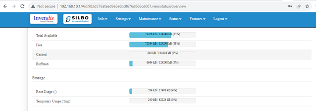
The specifications details are as follows.
| SN | Field name | Sample value | Description |
| 1 | Root Usage |
|
This field displays the total root usage of the device |
| 2 | Temporary Usage |
240 kB / 62124 kB (0%) |
This field displays the total temporary usage of the device |
Connection Tracking
In this section it displays the status of connection tracking for the device.
![]()
The specifications details are as follows.
| SN | Field name | Sample value | Description |
| 1 | Active Connection |
79 / 16384 (0%) |
This field displays the active connection of the device. |
DHCP Leases
In this section, it displays the DHCP lease of the temporary assignment of an IP address to a device on the network.
The specifications details are as follows.
| SN | Field name | Sample value | Description |
| 1 | Host Name | AnanyaA-LT | This field displays the configured Host Name/User Name for that device. |
| 2 | IPv4-Address | 192.168.10.123 | This field displays the IP address of the device. |
| 3 | MAC-Address | X:X:X:85:13:91 | This field displays the MAC-Address of the device. |
| 4 | Lease time remaining | 10h 4m 34s | This field displays the lease time remaining for the device. |
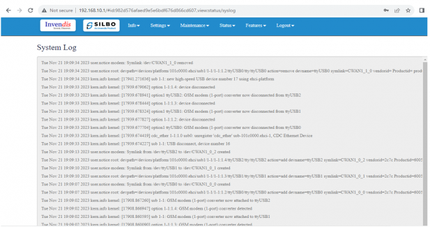
1.2 System Log
This page provides on screen System logging information.
In this page the user gets to view the system logs
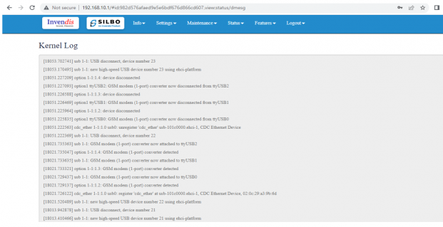
1.3 Kernel Log
This page provides on-screen Kernel logging information.
In this page, the user gets to view the Kernel logs
2. Setting
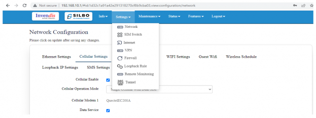
In this “Setting” module the user can Configure/update all the required parameters related to Network, SIM Switch, Internet, VPN, Firewall, Loopback Rule, Remote monitoring, Tunnel as per requirement.
IT consist of 8 submodules.
- Network
- Sim Switch
- Internet
- VPN
- Firewall
- Loopback Rule
- Remote Monitoring
- Tunnel
2.1 Network
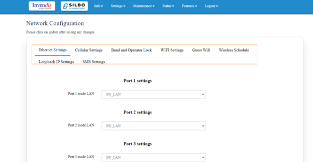
In this section the user does all the setting related configuration with reference to network like Ethernet Setting, Cellular Setting, Band lock and Operator Lock, Wi-Fi, Guest Wi-Fi, Wireless Schedule, SMS Setting, Loopback IP.
Ethernet Setting
In this page it will display all the configured port that is attached with the device.
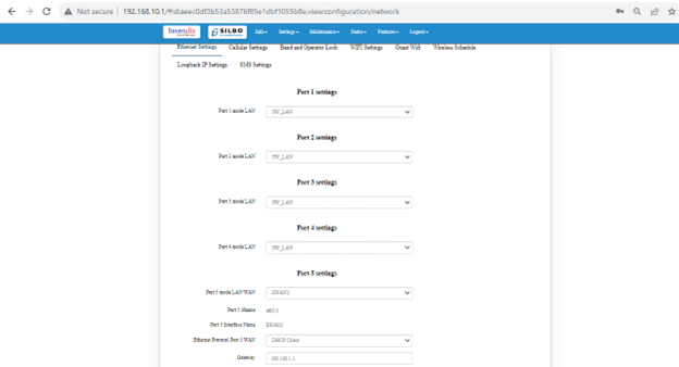
For this device 5 ports are configured. Ethernet mode can be configured as WAN and as LAN as well. Ethernet LAN Connection settings can be configured as DHCP server or Static.
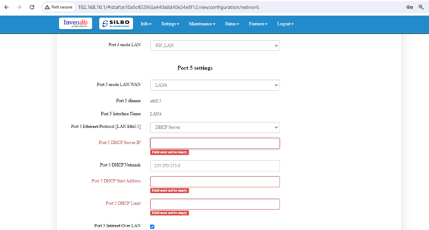
For port 5 setting
Kindly select the option LAN4 for Port 5 mode LAN/WAN. Based on the option selected the filed will also changes the user needs to configure all the required field and click on the save to save the required fields.
| SN | Field name | Sample value | Description |
| 1 | Port 5 mode LAN/WAN | LAN4 | This field displays the port mode selection |
| 2 | Port 5 ifname | eth0.5 | This field displays the ifname. |
| 3 | Port 5 Ethernet Protocol [LAN Eth0.1] | DHCP Server | This field displays the Ethernet mode selection |
| 4 | Port 5 DHCP Server IP | 192.168.10.1 | This field displays DHCP server IP configured. |
| 5 | Port 5 DHCP Netmask | 255.255.255.0 | This field displays DHCP server Netmask address configured |
| 6 | Port 5 DHCP Start Address | 100 | This field displays DHCP server start address configured |
| 7 | Port 5 DHCP Limit | 50 | This field displays DHCP server limit |
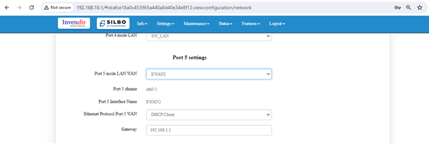
Kindly select the option EWAN2 for Port 5 mode LAN/WAN. Based on the option selected the filed will also changes the user needs to configure all the required field and click on the save to save the required fields.
| SN | Field name | Sample value | Description |
| 1 | Port 5 mode LAN/WAN | EWAN2 | This field displays the port mode selection |
| 2 | Port 5 ifname | eth0.5 | This field displays the ifname. |
| 3 | Port 5 Interface Name | EWAN2 | This field displays the Ethernet mode selection |
| 4 | Ethernet Protocol Port 5 WAN | DHCP client | This field displays the client |
| 5 | Gateway | 192.168.1.1 | This field displays gateway address configured |
Click on the save once all the configuration is done and click on the update button to update all the information.
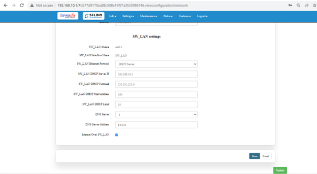
SW_LAN settings
In this part the user can configure the setting for SW_LAN
| SN | Field name | Sample value | Description |
| 1 | SW_LAN ifname | eth0.1 | This field displays the ifname. |
| 2 | SW_LAN Interface Name | SW_LAN | This field displays the interface name. |
| 3 | SW_LAN Ethernet Protocol | DHCP Server | This field displays the Ethernet mode selection |
| 4 | SW_LAN DHCP Server IP | 192.168.10.1 | This field displays DHCP server IP configured. |
| 5 | SW_LAN DHCP Netmask | 255.255.255.0 | This field displays DHCP server Netmask address configured |
| 6 | SW_LAN DHCP Start Address | 100 | This field displays DHCP server start address configured |
| 7 | SW_LAN DHCP Limit | 50 | This field displays DHCP server limit |
| 8 | DNS Server | 1 | This filed display number of DSN server availability |
| 9 | DNS Server Address | 8.8.8.8 | This filed display the DSN server address. |
After configuring all the required information, the user should click on the save and then click on the update to update the all the required information.
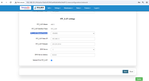
Static option for SW_LAN Ethernet Protocol
Select the option of static from the drop-down menu for SW_LAN Ethernet Protocol.
| SN | Field name | Sample value | Description |
| 1 | SW_LAN ifname | eth0.1 | This field displays the ifname. |
| 2 | SW_LAN Interface Name | SW_LAN | This field displays the interface name. |
| 3 | SW_LAN Ethernet Protocol | Static | This field displays the Ethernet mode selection |
| 4 | SW_LAN static IP | 192.168.5.1 | This field displays static server IP configured. |
| 5 | SW_LAN Netmask | 255.255.255.0 | This field displays static server Netmask address configured |
| 6 | DNS Server | 1 | This filed display number of DSN server availability |
| 7 | DSN Server Address | 8.8.8.8 | This filed display the DSN server address. |
After configuring all the required information, the user should click on the save and then click on the update to update the all the required information.
Cellular Setting
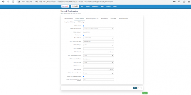
In this page, the user needs to configure the various details with respect to the SIM.
select single cellular single sim where the user must configure the APN details of the sim used for the router device. The Configurations can be done based on the SIM usage, with respect to IPV4 or IPV.
| SN | Field name | Sample value | Description |
| 1 | Cellular Operation Mode | Single Cellular with Dual Sim | This field displays the cellular operation mode. |
| 2 | Cellular Modem 1 | QuectelEC200A | This field displays the modem name. |
| 3 | Network Mode | Automatic | This field displays the Network mode selection |
| 4 | SIM 1 Access Point Name | airtelgprs.com | This field displays the name of the Sim 1 access point configured. |
| 5 | SIM 1 PDP Type | IPV4 | This field displays the type of SIM 1 |
| 6 | SIM 1 Username | This field is optional, and the user can configure the name of the SIM 1 | |
| 7 | SIM 1 Password | This field is optional, and the user can configure the password for the SIM 1 | |
| 8 | SIM 1 Authentication Protocol | None | This field displays the type of protocol is being used for SIM 1 |
| 9 | SIM 2 Access Point Name | airtelgprs.com | This field displays the name of the Sim 2 access point configured. |
| 10 | SIM 2 PDP Type | IPV4 | This field displays the type of SIM 2 |
| 11 | SIM 2 Username | This field is optional, and the user can configure the name of the SIM 2 | |
| 12 | SIM 2 Password | This field is optional, and the user can configure the password for the SIM 2 | |
| 13 | SIM 2 Authentication Protocol | None | This field displays the type of protocol is being used for SIM 2 |
| 14 | Primary SIM Switchback Time (In Minutes) | 10 | This field displays the time given for sim to swich in between. |
After configuring all the required information, the user should click on the save and then click on the update to update the all the required information.
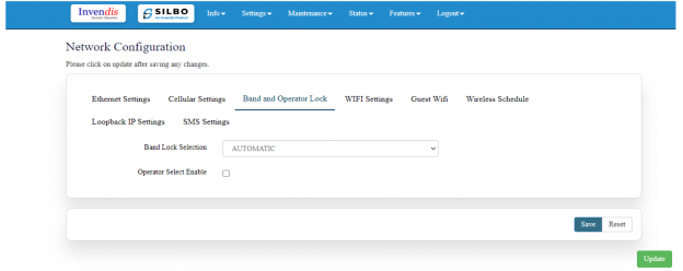
Band lock and Operator Lock
In this page, the user needs to configure the lock band and operator based on the service provider.
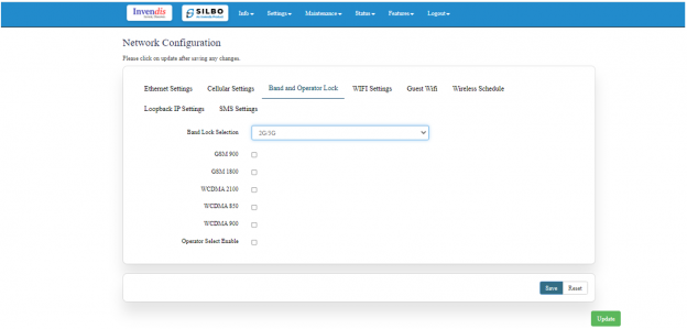
Bands available in the drop-down list.
2G/3G option
2G/3G: - 3G allows additional features such as mobile internet access, video calls and mobile TV. While the main function of 2G technology is the transmission of information through voice calls.
The user should select the band check box available for 2g/3g from the given list.
Bands available for selection under LTE for the bands available that zone.
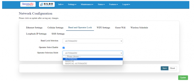
Operator Selection Mode
The user needs to click on the check box of the “operator select enable” to select the operator.
Once the check box is clicked there will be a dropdown list of the operator modes from which the user needs to select the mode. The user needs to select the operator mode from the given dropdown list.
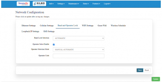
If the user selects the mode “Manual” or “Manual-Automatic” then one more text box will appear where the user must provide the operator code.
After configuring all the required information, the user should click on the save and then click on the update to update the all the required information.
Wi-Fi Setting
Wi-Fi is a family of wireless network protocols based on the IEEE 802.11 family of standards, which are commonly used for local area network of devices and internet access, allowing nearby digital devices to exchanges data by radio waves. These are the most widely used computer network, used globally in home and small office networks to link devices and to provided internet access with wireless router and wireless access point in public places. In this router has the general setting and change country code, channel, radio mode, radio passphrase as per the requirement after clicking on enable Radio button.
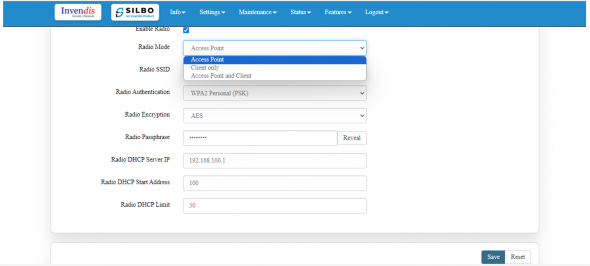
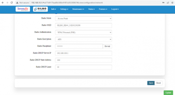
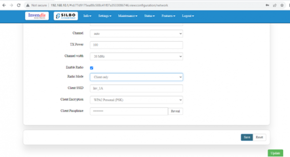
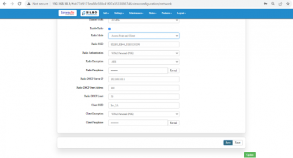
The user needs to select the respective radio mode based on its need. Basically, it has 3 radio mode.
Access Point mode: In Access Point mode, router connects to a wireless router through an Ethernet cable to extend the coverage of wireless signal to other network client.
Client point: In client mode, the access point connects your wired devices to a wireless network. This mode is suitable when you have a wired device with an Ethernet port and no wireless capability, for example, a smart TV, Media Player, or Game console and you want to connect it to the internet wirelessly, select the Client Mode and give the Radio SSID & client passphrase
Access point and client point: select this option for both type connection, give both SSID and passphrase.
After configuring all the required information, the user should click on the save and then click on the update to update the all the required information.
| SN | Field name | Sample value | Description |
| 1 | Radio 0 Protocol | IEEE 802.11 b/g/n | In this dropdown the user should select which protocol is being used |
| 2 | Country Code | INDIA | In this dropdown the user should select which county it belongs to . |
| 3 | Channel | Auto | In this dropdown the user should select the proper channel to be used . |
| 4 | TX Power | 100 | In this text box the user should specify the power. |
| 5 | Channel Width | 20 MHz | In this dropdown the user should select the channel width |
| 6 | Radio Mode | Access point | In this drop down the user should select the mode . |
| 7 | Radio SSID | SILBO_RB44_31B30230298 | In this text box the user should specify the SSID number |
| 8 | Radio Authentication | WPA2 Personal (PSK) | In this dropdown the user should select the type of authentication. |
| 9 | Radio Encryption | AES | In this dropdown the user should select the type of encryption required. |
| 10 | Radio Passphrase | In this text box the user should specify the password. | |
| 11 | Radio DHCP server IP | 192.168.100.1 | In this text box the user should specify the IP address of DHCP server. |
| 12 | Radio DHCP start address | 100 | In this text box the user should specify the start address of the DHCP. |
| 13 | Radio DHCP limit | 50 | In this text box the user should specify the limit for the DHCP. |
Wireless Schedule
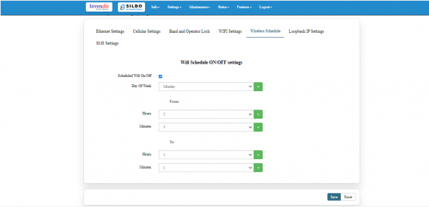
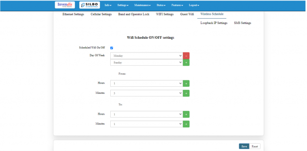
Wi-Fi can be automatically withdrawn based on the configuration done in this section.
The user can schedule the Wi-Fi’s accessibility time during a particular period.
After configuring all the required information, the user should click on the save and then click on the update to update the all the required information.
The user can select more than one “day of the week” for scheduling the wifi working hours.
Loop back IP settings
The loopback IP address, often referred to as “localhost”. it’s used to establish network connections within the same device for testing and troubleshooting purpose.
After configuring all the required information, the user should click on the save and then click on the update to update the all the required information.
The loopback IP address, commonly represented as 127.0.0.1, is a special address used for testing network connectivity on a local machine. It allows a device to send network messages to itself without involving external networks, making it useful for troubleshooting and diagnostics.
However, this IP can be changed as per requirement and to do that, Navigating to Setting>>Network configuration>> Loopback IP settings can be changed/updated.
Above screenshot shows the configuration window from GUI/WebUI
SMS Settings
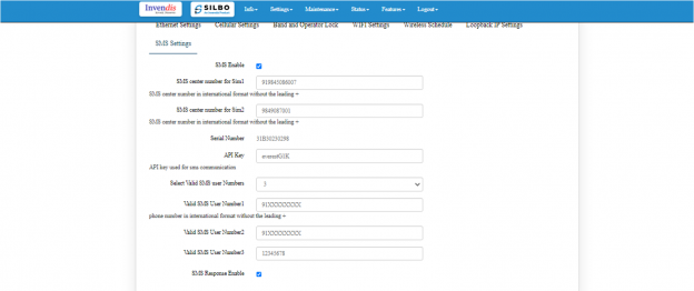
User needs to enable SMS option in SMS settings page. This option is to validate the mobile numbers using which controlling commands could be sent to the router device. 1 to 5 mobile numbers can be authenticated by choosing from “Select Valid SMS user numbers” and adding the mobile numbers below respectively. API key is the pass key used in the commands while sending SMS. Displayed in the below screen is the default API key which can be edited and changed as per choice. After addition of the mobile numbers user needs to click on save button for changes to take place.
Select valid user number max. 5 and add authorized phone number in the main menu where want to find the alert and click on SMS Response Enable, save and update button, now send SMS commands from the configured mobile number. Once the commands are received from the user phone number the board send acknowledgement as per the commands after that it will send the router’s status once it has rebooted and is operational again.
Mentioned below are a few commands which can be sent from the configured mobile number to the router device. Below two commands are One for rebooting the router device and another to get the uptime.
1) {"device":["passkey","API key"],"command":"reboot","arguments":"hardware"}
2) {"device":["passkey ","API key"],"command":"uptime"}
After configuring all the required information, the user should click on the save and then click on the update to update the all the required information.
2.2 SIM
In this page the user needs to configure the Sim for the given device.
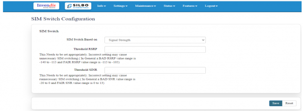
 The user needs to select from the drop-down menu on which basis the sim needs to be switched.
Once the user selects on “signal strength” then the parameters related to signal strength will pop up and the user needs to configure the parameters based on the requirement
Threshold RSRP
This Needs to be set appropriately. Incorrect setting may cause unnecessary SIM switching. ( In General a BAD RSRP value range is -140 to -115 and FAIR RSRP value range is -115 to -105).
Threshold SINR
This Needs to be set appropriately. Incorrect setting may cause unnecessary SIM switching. ( In General a BAD SNR value range is -20 to 0 and FAIR SNR value range is 0 to 13)
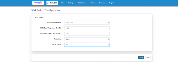
Once the user selects on “Data Limit” then the parameters related to Data Limit will pop up and the user needs to configure the parameters based on the requirement.
| SN | Field name | Sample value | Description |
| 1 | SIM Switch Based on | Data Limit | The user needs to select from the drop-down menu on what basis the sim needs to be switched. |
| 2 | SIM 1 Data Usage Limit (In MB) | 1000 | The user needs to set the limit for the data usage for SIM 1. |
| 3 | SIM 2 Data Usage Limit (In MB) | 1000 | The user needs to set the limit for the data usage for SIM 2. |
| 4 | Periodicity | Daily | The user needs to set the pattern/frequency to switch the sims. |
| 5 | Day Of Month | 16 | The user needs to set the day for switching the sim. |
After configuring all the required information, the user should click on the save.
2.3 Internet
In this page the user needs to configure the internet connection to set the priority from the various options. The user should decide what kind of connection it needs to provide to the device like LAN, WAN etc. Once the connections are configured then click on save option and then on update.
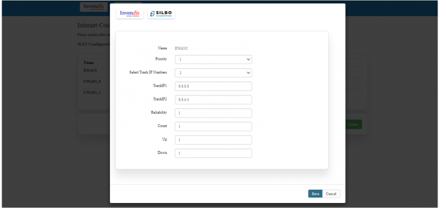
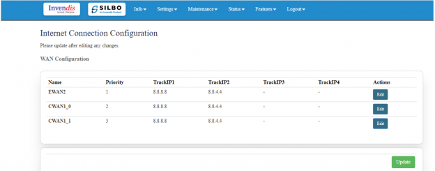 If the user needs to edit on the existing configuration, then the user should click on the “EDIT” button.
| SN | Field name | Sample value | Description |
| 1 | Name | EWAN2 | This field displays the name of the WAN connection |
| 2 | Priority | 1 | In this dropdown box the user need to select the priority. |
| 3 | Select Track IP Numbers | 2 | In this dropdown the user needs to select the track number for the Ips. |
| 4 | TrackIP1 | 8.8.8.8 | In this text field the user needs to set the IP address for the track 1 |
| 5 | TrackIP2 | 8.8.4.4 | In this text field the user needs to set the IP address for the track 1 |
| 6 | Reliability | 1 | Not sure what needs to be written |
| 7 | Count | 1 | Not sure what needs to be written |
| 8 | Up | 1 | Not sure what needs to be written |
| 9 | Down | 1 | Not sure what needs to be written |
Once the user is done with modification click on the save button to save all the changes and then click on the update button.
2.4 VPN
VPN stands for Virtual Private Network, it establishes a connection between the system and a remote server, which is owned by a VPN provider.
Creating a point-to-point tunnel that encrypts the personal data, masks the IP address, and allows to block the required website to blocks via firewalls on the internet.
There are 3 types of setting available under VPN configuration.
- General Settings
- IPSEC
- Open VPN
General Settings
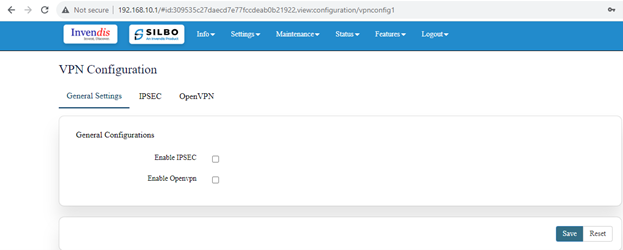
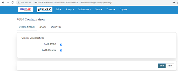
In this page the user must choose which type of VPN connection is required for the device.
The user must select from IPSEC or Open VPN based on its requirement. If required, the user can select for both the options.
The user needs to click on the save after selecting the option based on its requirement.
IPSEC
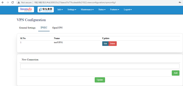
IPSEC VPN is used to create a VPN connection between local and remote networks. To use IPSEC VPN, the user should check that both local and remote routers support IPSEC VPN feature.
In this page the user can add/edit/delete the IPSEC VPN connection for the device.
The user needs to click on the update button once the required configuration is completed.
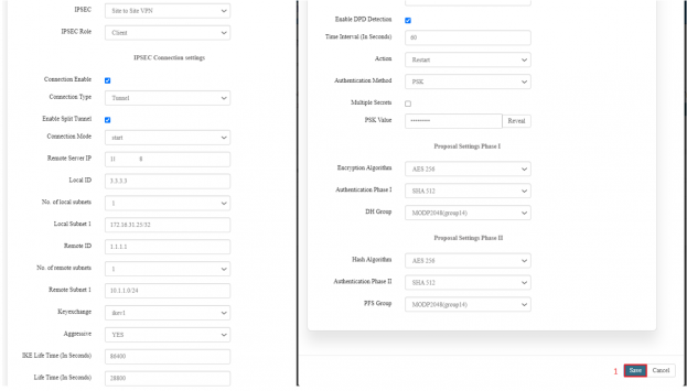
In IPSEC the user needs to click on edit button to edit the configuration of an existing VPN connection.
Click on the save button after the required configuration.
| SN | Field name | Sample value | Description |
| 1 | IPSEC | Site to Site VPN | In this dropdown the user should select the IPSEC connection type. |
| 2 | IPSEC Role | Client/Server | In this dropdown box the user needs to select the IPSEC role. |
| 3 | Connection Type | Tunnel | In this dropdown the user needs to select the connection type. The user should select on the connection enable check box. |
| 4 | Connection mode | start | In this drop down list the user should select the mode for the connection. it will have route/add/start/trap mode |
| 5 | Remote Server IP | 1.1.1.1 | In this text field the user needs to set the IP address for the remote server. |
| 6 | Local ID | g300 | The user needs to needs to set the local id . |
| 7 | No. of local subnets | 1 | In this dropdown the user needs to select how many subnet it will be connected. |
| 8 | Local Subnet 1 | 192.168.11.1/24 | In this text box the user needs to put the address of the local subnet. |
| 9 | Remote id | sophos | In this text box the user needs to put the id of the remote connection. |
| 10 | No of remote subnet | 1 | In this dropdown the user needs to select how many subnet it will be connected remotely. |
| 11 | Remote subnet | 192.168.10.0/24 | In this text box the user needs to put the address of the remote subnet. |
| 12 | Keyexchange | Ikev1 | Not sure what needs to be written. |
| 13 | Aggressive | Yes/No | Not sure what needs to be written. |
| 14 | IKE life time | 8 | Not sure what needs to be written |
| 15 | Lifetime in seconds | 1 | Not sure what needs to be written |
Open VPN
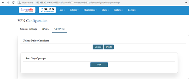
In the OpenVPN connection, the home network can act as a server, and the remote device can access the server through the router which acts as an OpenVPN Server gateway. To use the VPN feature, the user should enable OpenVPN Server on the router, and install and run VPN client software on the remote device.
The user needs to upload the respective certificate from a valid path and then click on the “Start”.
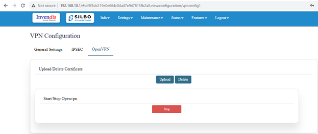
Once the openvpn connection starts the user will get an option to stop the VPN connection as and when required. By clicking on the Stop button, the user can stop the VPN connection.
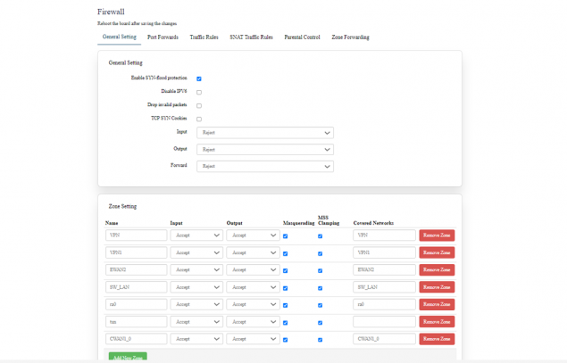
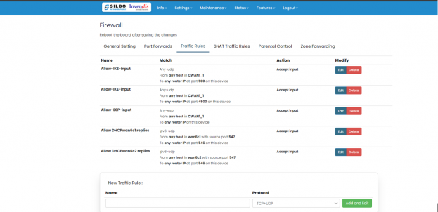
2.5 Firewall
A firewall is a layer of security between the network and the Internet. Since a router is the main connection from a network to the Internet, the firewall function is merged into this device. Every network should have a firewall to protect its privacy.
There are 6 types of setting available under firewall.
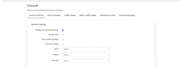
- General Settings
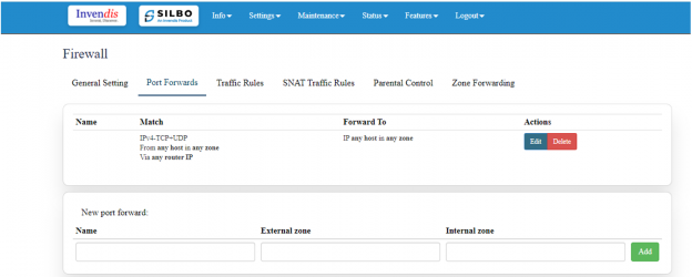
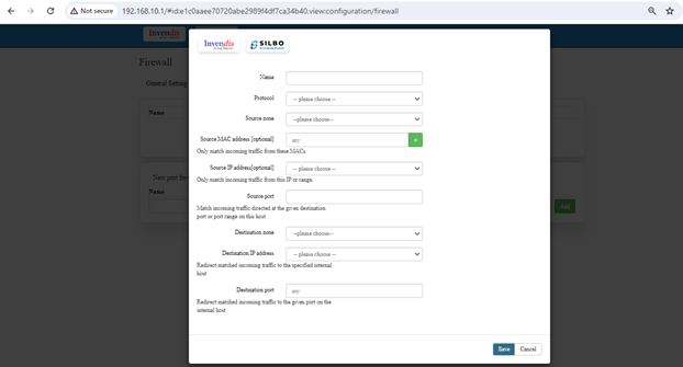
- Port forwards
- Traffic Rules
- SNAT traffic Rules
- Parental Control
- Zone Forwarding
Need more info to write about firewall and its category.
General Setting
Port Forward
EDIT
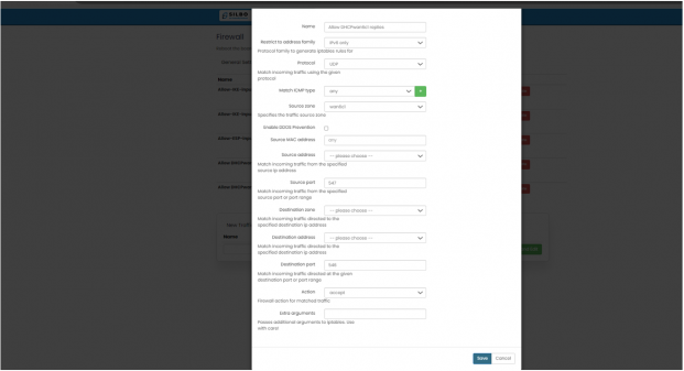
Traffic Rule
EDIT
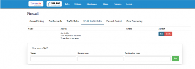
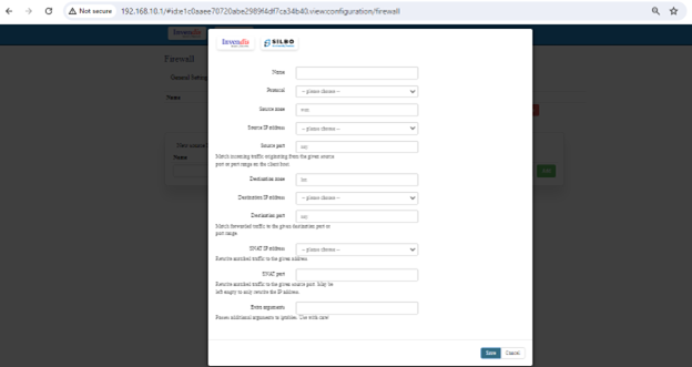
SNAT Traffic Rule
Edit
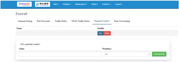
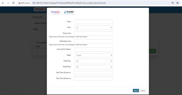
Parental Control
Edit
Zone Forwarding
EDIT
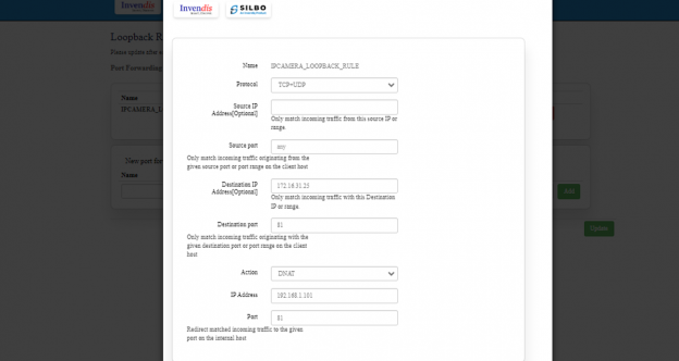
2.6 Loopback Rule
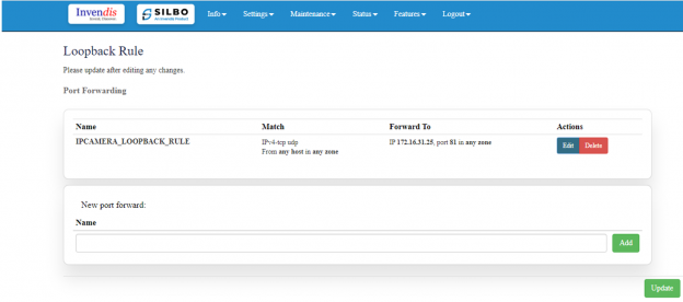
In this page the user can configure the port where he want to forward the traffic to. Here the user can add/edit/delete different port ports as per the requirement.
The user should click on add/edit to do the required changes in the port and enter the valid information in each section to configure the port for forwarding.
Once the user is done with the required configurations, should click save button and then click on the update to save the changes.
2.7 Remote Monitoring
In this page the user can select which equipment needs to be monitor remotely, the TR-069 device or the NMS device.
One the user selects the type of RMS click on the save.
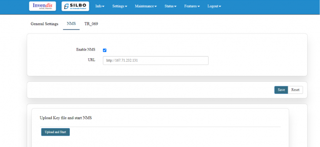
NMS
IN this page the user should type the server IP or domain name in the URL then click on sav. Click on upload and start (Once key is uploaded and this option is clicked, NMS automatically starts, and this router device gets registered with the NMS server provided.
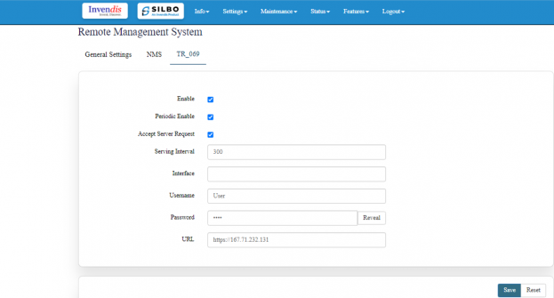
TR069
To enable the TR069 the user needs to click on the enable check box.
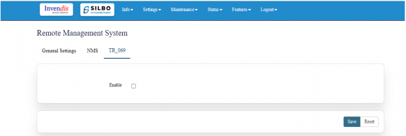
Once the user clicks on the check box of enable it will display all the required filed to configured.
| SN | Field name | Sample value | Description |
| 1 | Serving Interval | 300 | This displays the interval time |
| 2 | Interface | Not sure what needs to be written | |
| 3 | Username | Username | The user needs to mention the username |
| 4 | Password | ****** | The user should set the password |
| 5 | URL | The user needs to mention the URL |
The user should fill all the required fields and click on the save button.
2.8 Tunnel
Tunnels are a method of transporting data across a network using protocols which are not supported by that network.
General Settings
In this page the user needs to select under which type of tunnel it needs to send the data.
Once the user selects the type of tunnel then click in the save button.
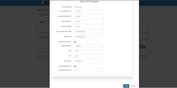
GRE Tunnel
In this page the user needs to add all the details of GRE tunnels.
Once the user configured all the required fields then it needs to click on the save.
Here the user can add/edit/delete the details of the tunnel. Once the required update is done then it needs to click on update to save the changes.
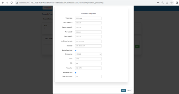
IPIP Tunnel
In this page the user needs to add all the details of IPIP tunnels.
Once the user configured all the required fields then it needs to click on the save.
Here the user can add/edit/delete the details of the tunnel. Once the required update is done then it needs to click on update to save the changes.
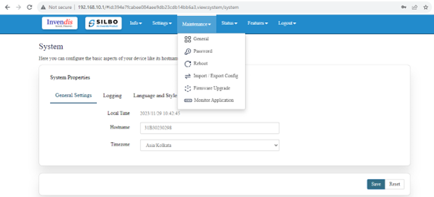
3 Maintenance
In this module the user can configure/upgrade/modify the settings related to system, password, firmware and monitoring.
It includes below submodules.
- General
- Password
- Reboot
- Import and Export config
- Firmware upgrade
- Monitor Application
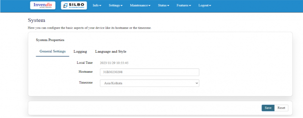
3.1 General
In this section the user can configure the details related to time zone and host name
| SN | Field name | Sample value | Description |
| 1 | Local Time | 2023/12/13 12:24:11 | It displays the system current date and time. |
| 2 | HostName | 31B30230298 | It displays the host name. |
| 3 | Timezone | Asia/Kolkata | It displays in which time zone its configured. |
Once the user configures the required details then click on the save button to save all the details.
Logging
Here the user can configure the basic aspects of your device related to system.
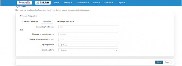
| SN | Field name | Sample value | Description |
| 1 | System log buffer size | 32 | This displays the log size of system buffer |
| 2 | External system log server | 0.0.0.0 | This displays the ip add of the external system log |
| 3 | External system log server port | 514 | This displays the port number of the external system log |
| 4 | Log output level | debug | In this drop down the user selects the level of the log output. |
| 5 | Cron Log level | debug | In this drop down the user selects the level of the corn log . |
Once the user configures the required details then click on the save button to save all the details.
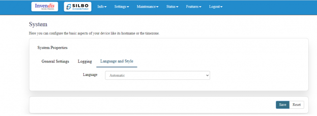
Language and Style
Here the user can configure the basic aspects of your device related to language.
Once the user configures the required details then click on the save button to save all the details.
3.2 Password
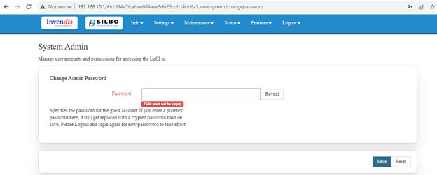
In this module the user can set the password for the admin credentials.
Specifies the password for the guest account. If the user enter a plaintext password here, it will get replaced with a crypted password on save. The new password will be effective once the user logs out and log in again.
The user needs to write the password in the text box and click on the save button to save the password.
3.3 Reboot
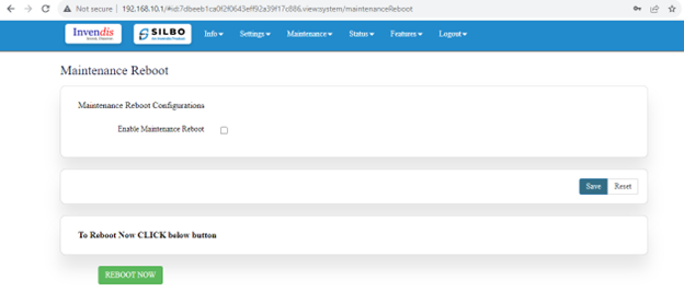
In this module the user can reboot the device remotely.
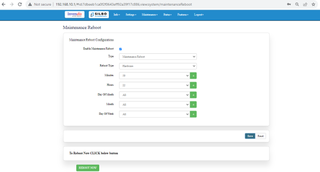
To start the reboot process first the user needs to fill all the required fields.
Need to select the type of reboot for the device whether it needs to be Hardware or Software reboot.
| SN | Field name | Sample value | Description |
| 1 | Type | Maintenance Reboot | In this dropdown list the user needs to select the type of reboot is required to configure. |
| 2 | Reboot Type | Hardware | In this dropdown list the user needs to select the hardware or software reboot is required. |
| 3 | Minutes | 59 | In this dropdown the user needs to configure the min to start the reboot activity |
| 4 | Hours | 22 | In this dropdown the user needs to configure the hours to start the reboot activity |
| 5 | Day of Month | All | In this dropdown the user needs to configure the day of the month to start the reboot activity |
| 6 | Month | All | In this dropdown the user needs to configure the month to start the reboot activity |
| 7 | Day of the week | All | In this dropdown the user needs to configure the week to start the reboot activity |
Once the user fills all the required given parameters click on the save.
To start the reboot process, click on the “Reboot Now” button.
3.4 Import and Export
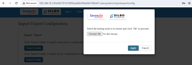
In this section, User can Import & Export Configuration files of the Device.
click “Export Config” to export device configuration & settings to a text file,
click “Import Config” to import device configuration & settings from a previously exported text file.
The user need to select on the choose file to and click on the apply.
3.5 Firmware Upgrade
The user can upgrade with the latest software for the existing firmware.
Click on the flash image and chose the path where the sys-upgrade file is kept and then click on flash image, it will upgrade to the latest software once the reboot is done.
Click on the Retain Config and flash and chose the path where the sys-upgrade file is kept and then click on Retain Config and flash, it will upgrade to the latest software once the reboot is done.
Click on the Factory Reset for the complete retest of the device.
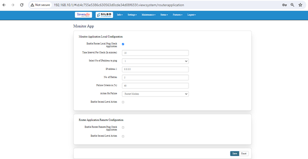
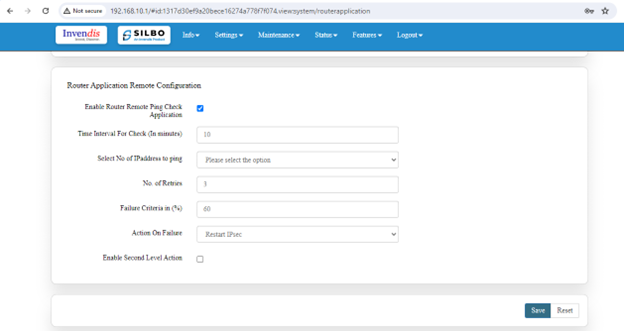
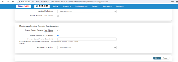
3.6 Monitor Application
4 Status
In this module the user can view the status of the router device with respect to the network, Wan, modem etc.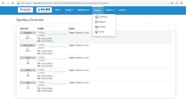
It has 4 submodules.
- Interfaces
- Internet
- Modem
- Route
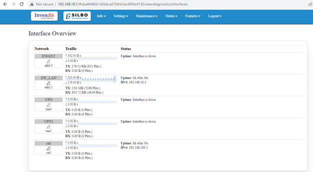
4.1 Interfaces
In this page the user can see the traffic status for all the network through which the device works.
Looking on the network status the user can check if the cellular or the ethernet is up.
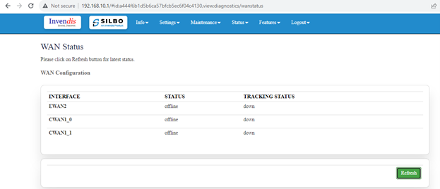
4.2 Internet
In this submodule the user can view the status of the internet connections.
To see the latest status of the internet connection the user needs to click on the refresh button.
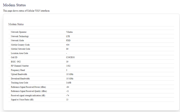
4.3 Modem
In this sub module the user will get to know the status of the cellular interface which is installed inside the modem. The user can view all the details related to the sim in terms of Operator, Network technology, Mobile country code, Upload bandwidth, Download Bandwidth, Frequency band, RSRP, RSRQ, RSSI & SNR under this page.
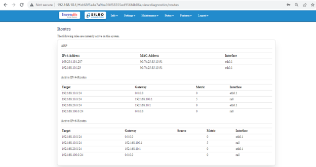
4.4 Route
In this page the user can check the status of the route for the device. The ARP status can be visible in under this page.
5 Features
In this module the user can see all the features that the router device has.
This module includes the below features.
- Mac Address Binding
- URL Filtering
- Web Server
- Wi-Fi MacID Filtering
- Routing
- Others
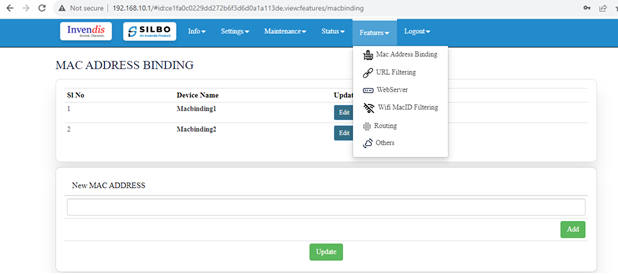
5.1 Mac Address Binding
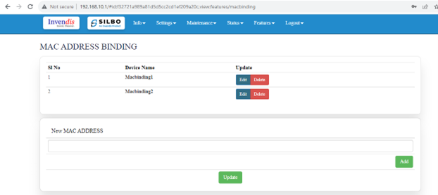
Under this submodule the user can configure/update/edit the IP Address for MAC
The user should write MAC address and then click on the add button. Once the address is added then click on the update button to save the modification.
The user needs to click on the Edit button to modify the preexisting configuration.
Once the user modifies the MAC address /IP Address then click on the save button to save the changes done.
The user can click on the deleted button to delete an existing configured device.
Post all the changes the user needs to click on the update to reflect all the changes in the application.
5.2 URL Filtering
In this submodule the user should provide the URL which needs to be blocked for the device.
To add the new URL for blocking, click on the Add New button.
Once the user clicks on the Add New button a new pop will appear in that page write the URL and click on the save. The user can select the status of that URL while defining the URL.
To edit / delete the existing URL the user needs to click on the edit /deleted button respectively.
Click on the save after the changes are done as per the need.
5.3 Web Server
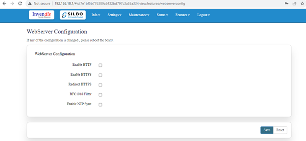
In this submodule the user can configure webserver related parameters.
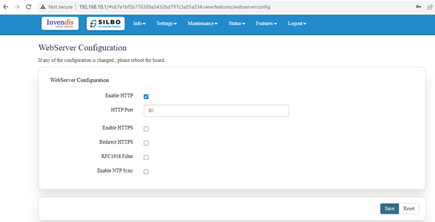
To configure the HTTP, click on the enable HTTP. Once the user clicks on the check box the HTTP Port text box will appear where the user needs to configure the port id.
Click on save buttons to save the changes.
To configure the 2nd HTTP, click on the enable HTTP. Once the user clicks on the check box the HTTP Port text box will appear where the user needs to configure the port id.
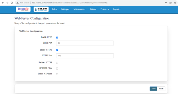 Click on save buttons to save the changes.
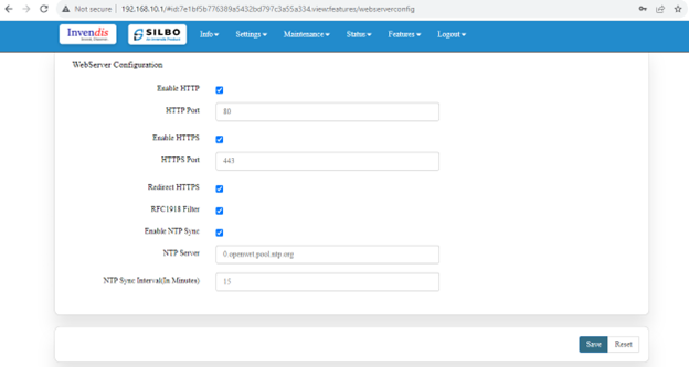
Click on the “Redirect https” and “RFC1918 Filter” check box to respectively and click on the save button to save the changes.
To configure the NTP sync, click on the enable NTP sync. Once the user clicks on the check box the respective text boxes will appear to configure the parameters.
Once the user configures the parameters click on the save button to save the given values.
5.4 Wi-Fi MacID Filtering
In this module the user can filter the Macids. Mac address filtering allows users to block traffic coming from certain known machines or devices.
Before adding the MacIDs the user needs to select the mode from the dropdown menu.
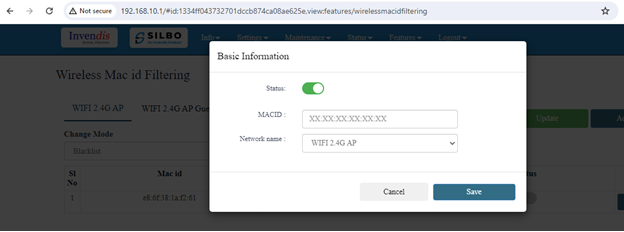
To Add the MacID the user needs to click on Add New option select the mac id and network name Wi-Fi 2.4G AP OR Wi-Fi 2.4G AP Guest, select enable/disable option and save it and update.
Once the required MACID and Network Name is configured the user needs to click on the save button to add the details.
The user needs to click on the edit button to do modifications on the pre-existing configuration.
Once the required MACID / Network Name is modified the user needs to click on the save button to reflect the changed value in the application.
WIFI 2.4G AP Guest
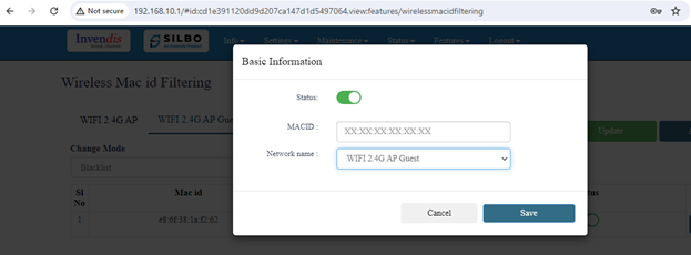
To Add the MacID the user needs to click on Add New option select the mac id and network name Wi-Fi 2.4G AP Guest, select enable/disable option and save it and update.
Once the required MACID and Network Name is configured the user needs to click on the save button to add the details.
The user needs to click on the edit button to do modifications on the pre-existing configuration.
Once the required MACID / Network Name is modified the user needs to click on the save button to reflect the changed value in the application.
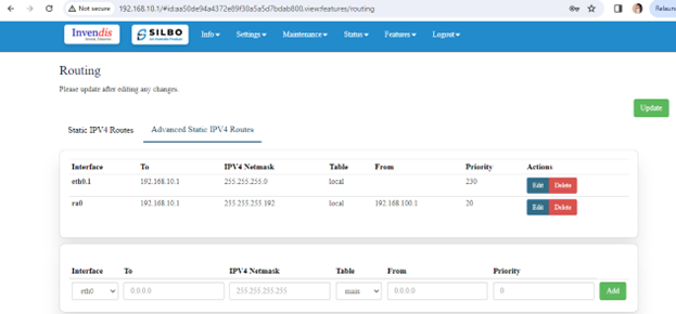
5.5 Routing
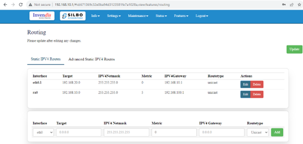
In this submodule the user can configure the parameters related to routing of the device. like Target address, Networks address etc.
To add a new device the user needs to fill all the required information and click on the add button.
| SN | Field name | Sample value | Description |
| 1 | Interface | eth0.1 | In this drop down list the user should configure the interface name. |
| 2 | Target | 192.168.10.1 | In this text box the user needs to insert the target IP address |
| 3 | IPV4 Netmask | 255.255.255.0 | In this text box the user should give the address for the IPV4Netmask |
| 4 | Metric | 5 | In this text box the user should insert the number of the metric. |
| 5 | IPV4 Gateway | 192.168.100.1 | In this text box the user should configured the address for the IPV4 Gateway. |
| 6 | Route Type | Unicast | In this drop down box the user should select the type of route needed for the device. |
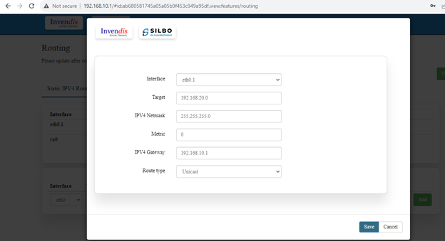
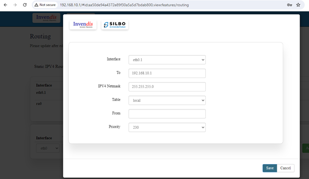
To edit the existing device the user needs to click on the edit option.
Once the changes are done click on the save button to save all the changes.
Click on the deleted button to delete the existing device detail.
To add a new device the user needs to fill all the required information and click on the add button.
| SN | Field name | Sample value | Description |
| 1 | Interface | eth0.1 | In this drop down list the user should configure the interface name. |
| 2 | To | 192.168.10.1 | In this text box the user needs to insert the target IP address |
| 3 | IPV4 Netmask | 255.255.255.0 | In this text box the user should give the address for the IPV4Netmask |
| 4 | Table | local | |
| 5 | From | 192.168.100.1 | In this text box the user should configured the from address for the routes |
| 6 | Priority | 230 |
To edit the existing device the user needs to click on the edit option.
Once the changes are done click on the save button to save all the changes.
Click on the deleted button to delete the existing device detail.
Once all the configurations are done click on the update button to reflect the changes made.
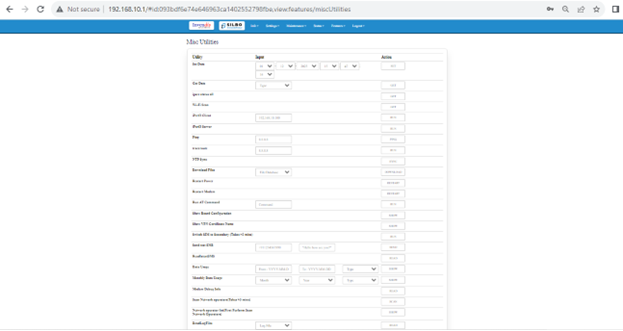
5.6 Others
In this page the user will get to do all the other miscellaneous configuration with respect to the device based on the required parameters.
| SN | Utility | Action | Description |
| 1 | Set Date | SET | Need to set the date and time and after click command get the Date and time |
| 2 | Gate Date | GET | Needs to get the system date and time |
| 3 | IPsec status all | GET | Needs to get the IPsec details |
| 4 | Wi-Fi Scan | GET | Needs to get the Wi-Fi status |
| 5 | ipref3 client | RUN | Needs to click on the RUN to execute the command |
| 7 | ipref3 server | RUN | Needs to click on the RUN to execute the command |
| 8 | Ping | PING | Needs to click on the ping status |
| 9 | Traceroute | RUN | Needs to click on the ping Traceroute status |
| 10 | NTP Sync | SYNC | Click to Sync the NTP |
| 11 | Download Files | DOWNLOAD | Click to Download the files /Database |
| 12 | Restart Power | RESTART | Click Restart the power |
| 13 | Restart Modem | RESTART | Click to Restart the modem |
| 14 | Run at command | RUN | Click to Run the command |
| 15 | Show board configuration | SHOW | To Show the board configuration |
| 16 | Show VPN Certificate Name | SHOW | To Show VPN Certificate Name |
| 17 | Switch SIM to Secondary | RUN | Click to switch the SIM to secondary mode |
| 18 | Send Test SMS | SEND | To Send the SMS Confirmation |
| 19 | Readlatest SMS | READ | Click to Read the latest SMS |
| 20 | Data Usage | SHOW | Click to show the data usage. |
| 21 | Monthly Data Usage | SHOW | Click to show the monthly data usage |
| 22 | Modem debug Info | READ | Click to read the information about the modem debug |
| 23 | Scan Network operators (take>3mins) | SHOW | Click to show the Network operator |
| 24 | Network operators (first perform scan network operator | SHOW | Click to show the Network operator |
| 25 | ReadLogFiles | READ | Click to read the log files |
| 26 | Enable ssh | RUN | Click to Run the command |
| 27 | Disable ssh | RUN | Click to Run the command |
| 28 | Clear SIM1 Data | CLEAR | Click to clear the SIM1 data |
| 29 | Clear SIM2 Data | CLEAR | Click to clear the SIM data |
6 Logout
The user should click on log out option to logged out from the router application.
The user needs to click on the ok to come out of the router application.

