Log in to the router by typing the proper “URL” in your browser with its username and password and the page is shown as Figure-1.1.
Figure-1.1: Login Page
1.2 Home page
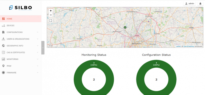
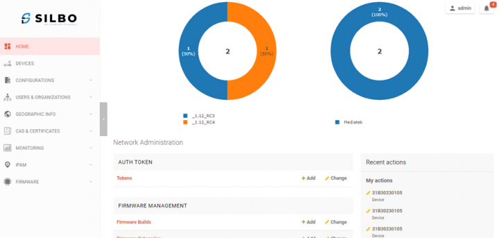
Once you key in the Username and Password, by default landing with the Home page, and the page is shown as Figure-1.2a & 1.2b.
Here, in the Home Page you can see all the information related to “Monitoring Status”, “Configuration Status”, “Device Models”, “Firmware Version” and “Network Administration”.
On the Top-Right corner, you have “Notifications” and “Admin” to change the Password / Logout
On the Left-side, you have Network configurations, Users & Organizations, Geographical Information, Public Key Infrastructure, Network Monitoring, Firmware Management. Figure-1.2a: Home PageFigure-1.2b: Home PageOn the Left-side, you have Network configurations, Users & Organizations, Geographical Information, Public Key Infrastructure, Network Monitoring, Firmware Management.
2. Devices
Here all the Device related Network Configurations can be updated which are applicable for a specific Site device only.
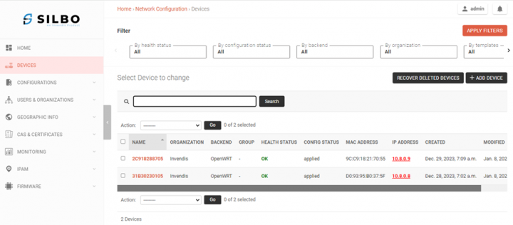
Select option Devices on the left-side to navigate to Devices information.
You have an option to “Filter” on the Top, by default all the Filter options are “All”.
Once the NMS is enabled in a device, you can see that Device / Site details as shown in Figure-2. Figure-2: Devices Details
2.1 Overview
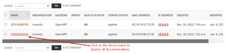
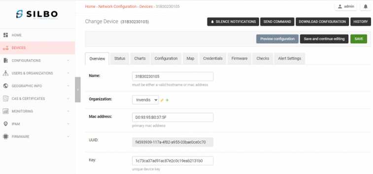
Click on the device name to navigate to that device details as shown in Figure-2.1a.Figure-2.1a: Devices Details
By default, the page will be shown with the Overview details for that device as shown in Figure-2.1b & 2.1c.
Generally, it’s not required to modify the configuration. If you want to modify any configuration in this page, update the details and click on “Save and continue editing” or “Save” button. Figure-2.1b: Device OverviewFigure-2.1c: Device Overview
2.2 Status
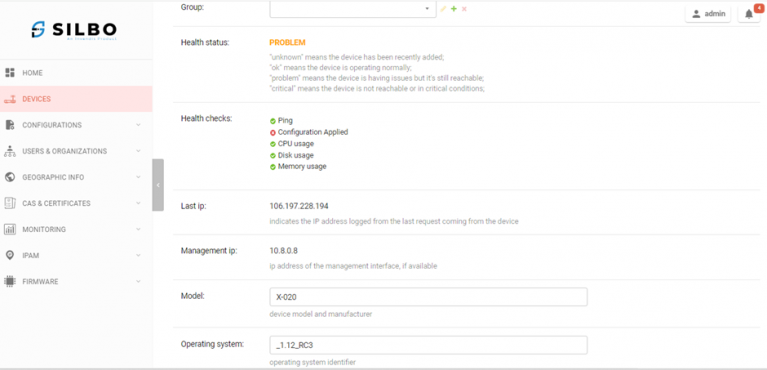
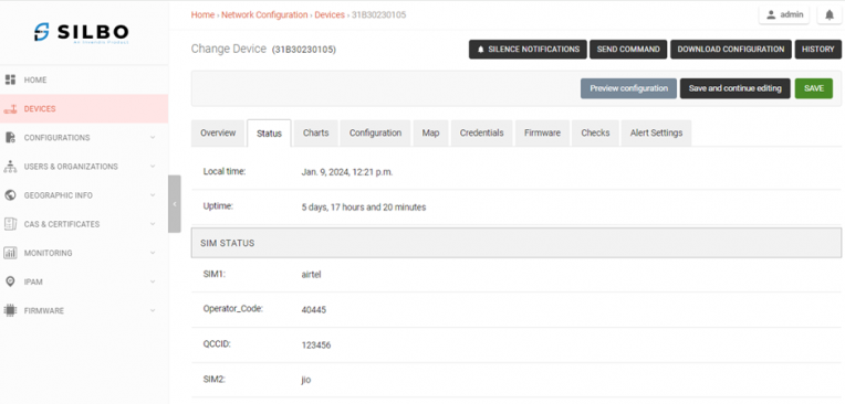
Click on the “Status” Tab and the page as shown in Figure-2.2.
In this Status page, you can see the “SIM STATUS” of both SIM1 & SIM2, “CPU”, “RAM STATUS”, “STORAGE”, “INTERFACE STATUS” of Ethernets / Wi-Fi / Tunnel / SIM separately, “DHCP LEASES”, “NEIGHBORS” by scrolling up/down.Figure-2.2: Device Status
2.3 Charts
Click on the “Charts” Tab and the page as shown in Figure-2.3.
You can choose the period of “1 day / 3 days / 1 week / 1 month / 1 year” for generating the Charts.
Also, the Charts can be exported to .csv format by clicking on “export data” button.
In this Charts page, you can see the Charts of “Up Time”, “Signal Strength”, “N/W Access Technology”, “Packet Loss”, “Traffic” of Ethernets / Wi-Fi / Tunnel / SIM separately, “Memory Usage”, “CPU Load”, “Disk Usage” by scrolling up/down.Figure-2.3: Device Charts
2.4 Configuration
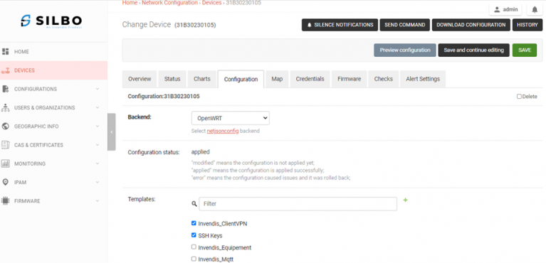
Click on the “Configuration” Tab and the page as shown in Figure-2.4a.Figure-2.4a: Device Configuration
Generally, it’s not required to modify the configurations for device specific.
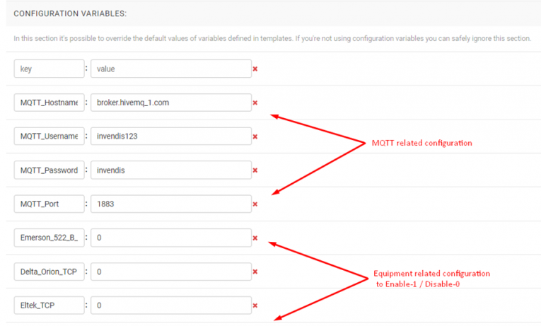
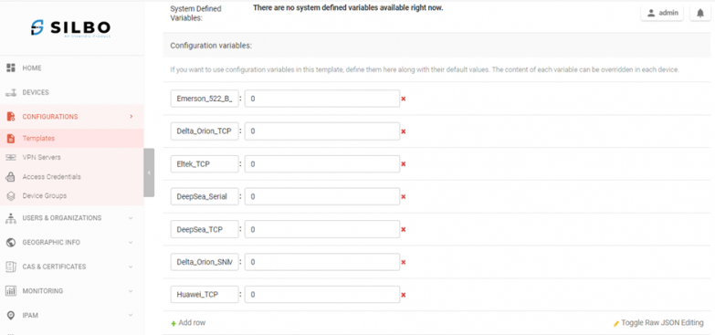
By default, in the “Templates” section the “Invendis_Equipment” and “Invendis_Mqtt” is not enabled. If required to enable, click on the checkbox to enable it. But this configuration changes will be applicable for this device only.
Once the checkbox is ticked , the related details will show under “Configuration Variables” section and if multiple checkboxes are ticked at a time, then it shows one after the other as shown in the Figure-2.4b.
Click on “Save and continue editing” or “Save” button once the details are updated. Figure-2.4b: Device Configuration
2.5 Map
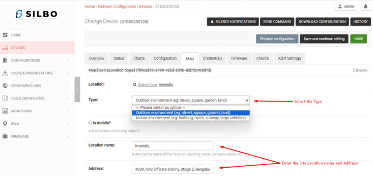
Click on the “Map” Tab and the page as shown in Figure-2.5.
Choose the Type from drop-down and enter the Site location name and Address details to update the location.
Click on “Save and continue editing” or “Save” button once the details are updated.Figure-2.5: Device Map
2.6 Credentials
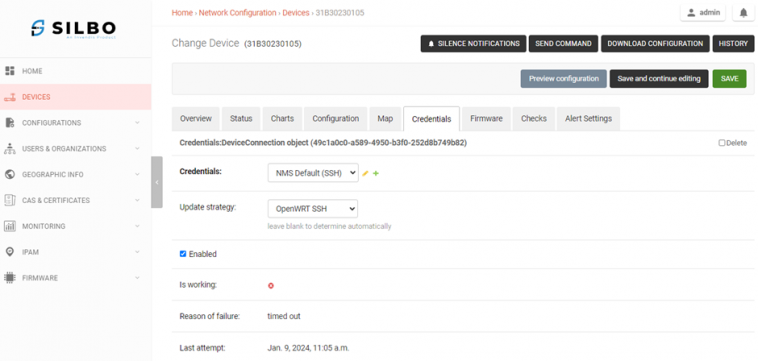
Click on the “Credentials” Tab and the page as shown in Figure-2.6.Figure-2.6: Device Credentials
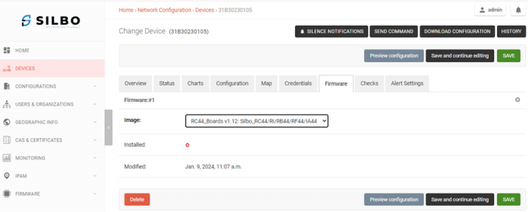
2.7 Firmware
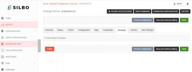
Click on the “Firmware” Tab as shown in Figure-2.7a.Figure-2.7a: Device Firmware
Click on the “+Add Another Firmware” and choose the proper image to upload as shown in Figure-2.7b.Figure-2.7b: Device Firmware Image
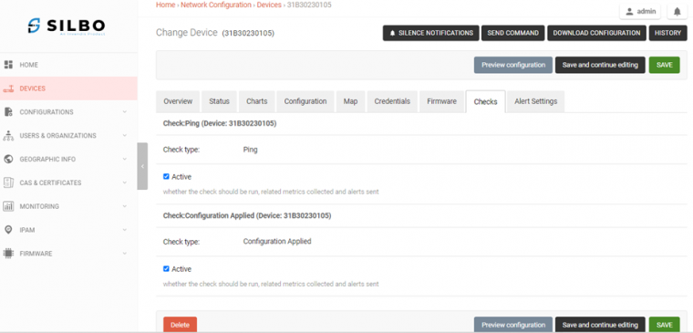
2.8 Checks
Click on the “Checks” Tab as shown in Figure-2.8.
In this page, you can see the “Ping” and “Configuration Applied” Checks.Figure-2.8: Device Checks
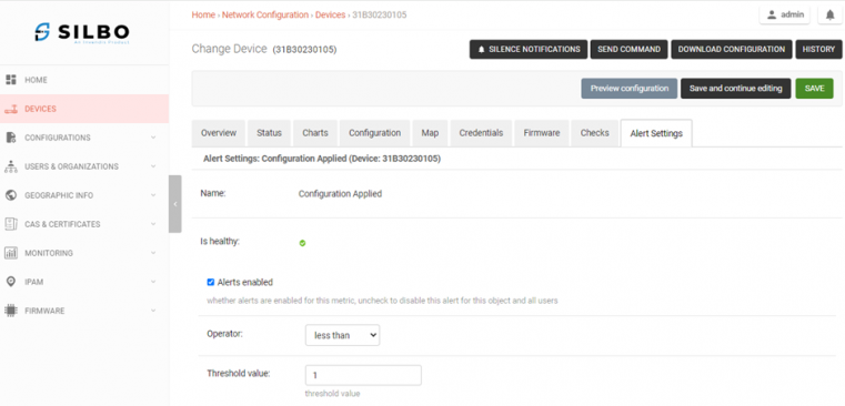
2.9 Alert Settings
Click on the “Alert Settings” Tab as shown in Figure-2.9.
By default, all the Alert Settings are Enabled for “Configuration Applied”, “Memory Usage”, “Disk Usage”, “Ping”, “CPU Usage”.
You can modify the threshold values for generating Alerts.
Click on “Save and continue editing” or “Save” button once the details are updated.Figure-2.9: Device Alert Settings
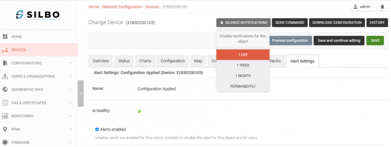
2.10 Silence Notifications
Click on the “Silence Notifications” button and choose the option for how long notifications should be disabled either 1 Day / 1 Week / 1 Month / Permanently as shown in Figure-2.10.Figure-2.10: Silence Notifications
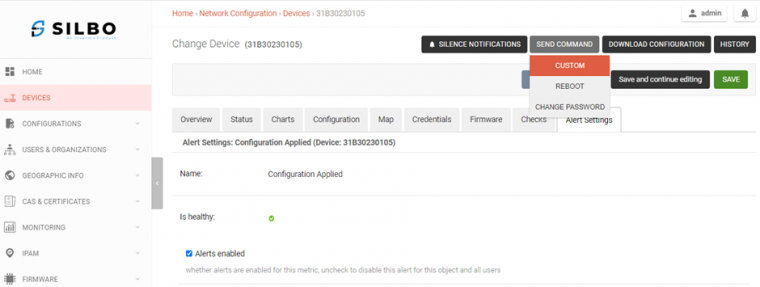
2.11 Send Command
Click on the “Send Command” button and choose the option “Custom” / “Reboot” / “Change Password” to execute those commands as shown in Figure-2.11.Figure-2.11: Send Command
3. Configurations
Here the Network Configurations can be updated which are applicable for all Site devices.
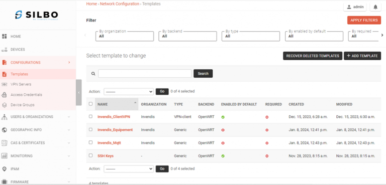
3.1 Templates
Navigate to Configurations and Select option Templates on the left-hand side.
The Templates page looks as shown in Figure-3.1.
By default, the “Invendis_ClientVPN” and “SSH Keys” Templates are enabled while setting up the NMS Server.Figure-3.1: Templates
3.1.1 Creating New Template
Click on the “+ADD TEMPLATE” button on the right-hand side as shown in Figure-3.1.1.
Click the checkbox þ to Enable and by scrolling down update the “configuration variables” details.
Click on “Save and continue editing” or “Save” button once the details are updated.
Figure-3.1.1: Add Template
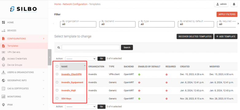
3.1.2 Editing Existing Template
Click on the Name to edit the configurations as shown in Figure-3.1.2a.Figure-3.1.2a: Edit Template
Click on the “Invendis_Equipment” / “Invendis_Mqtt” Name to edit the configurations.
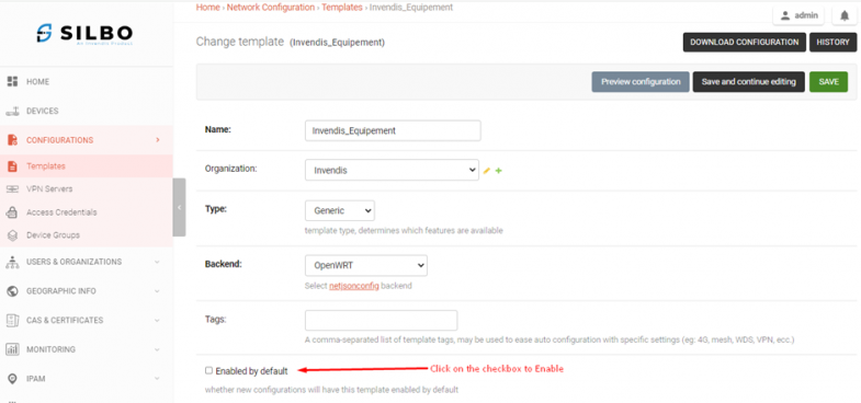
Click the checkbox þ to Enable and by scrolling down update the “configuration variables” details as shown in Figure-3.1.2b & 3.1.2c.
Click on “Save and continue editing” or “Save” button once the details are updated.Figure-3.1.2b: Enable TemplateFigure-3.1.2c: Template configurations.
4.Users & Organizations
Here the Users & Organizations can be updated which are applicable for all the Users and Organizations.
4.1 Users
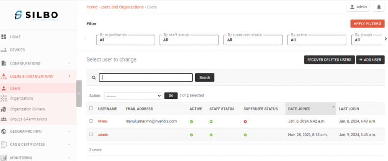
Navigate to Users & Organizations and Select option Users on the left-hand side.
The Users page looks as shown in the below screenshot.
By default, the “admin” Username is enabled while setting up the NMS Server.Figure-4.1: User Details
4.1.1 Creating New User
Click on the “+ADD USER” button on the right-hand side.
Enter the configuration details such as Username, Email, Password and Personal Info if you needed.
Then you need to give permissions as a “Staff” or “Superuser” or both it depends on your User by selecting those checkboxes þ. In Groups select Operator or Administrator or both based on permissions granted to each of their groups as shown in Figure-4.1.1a.
After selecting Groups, select Organization in drop-down menu that this New User belongs to which Organization as shown in Figure-4.1.1b.
Click on “Save and continue editing” or “Save” button.
Note: “Superuser” permission is not recommended other than “Admin” user.
Figure-4.1.1a: Add User PermissionsFigure-4.1.1b: Add User Organization
4.1.2 Editing Existing User
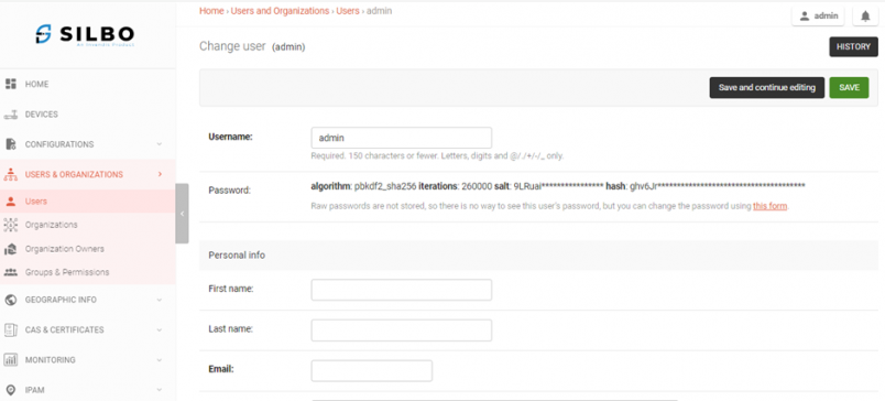
Generally, it’s not required to modify the configurations. If required, click on the “admin” Name to edit the configurations.
Update the configuration details as shown in Figure-4.1.2.
Click on “Save and continue editing” or “Save” button.Figure-4.1.2: Edit User Details
4.2 Organizations
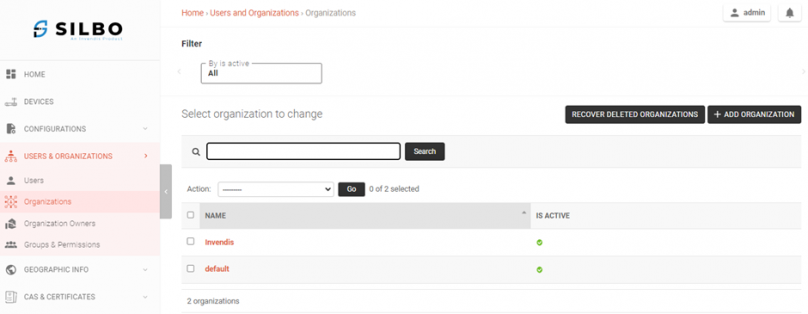
Navigate to Users & Organizations and Select option Organizations on the left-hand side.
The Organizations page looks as shown in Figure-4.2.Figure-4.2: Organizations
4.2.1 Creating New Organization
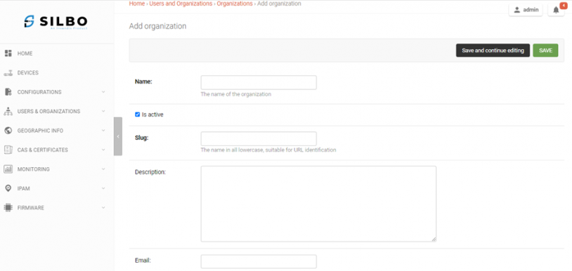
Click on the “+ADD ORGANIZATION” button on the right-hand side.
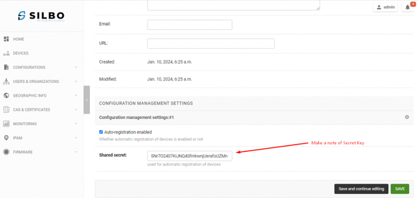
Enter the configuration details such as New_CustomerName, Email_ID and leave the rest of the things as it is and make a note of Shared secret key generated for New Organization as shown in Figure-4.2.1a & 4.2.1b.
Click on “Save and continue editing” or “Save” button.Figure-4.2.1a: Add OrganizationFigure-4.2.1b: Note Organization Secret Key
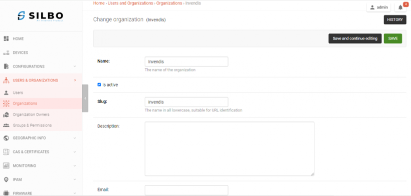
4.2.2 Edit Existing Organization
Click on the “Name” Name to edit the configurations.
Update the configuration details as shown in Figure-4.2.2.
Click on “Save and continue editing” or “Save” button.Figure-4.2.2: Edit Organization
4.3 Organization Owners
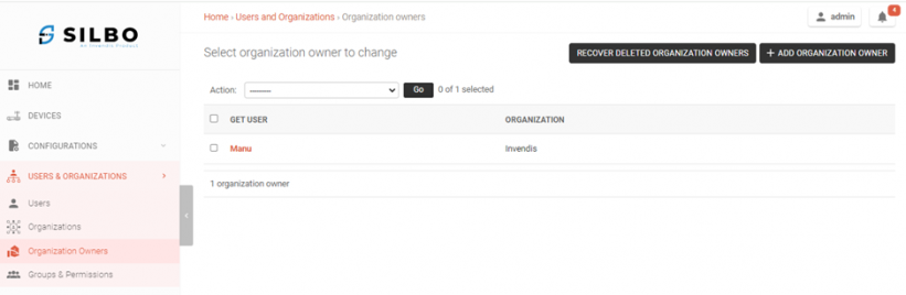
Navigate to Users & Organizations and Select option Organization Owners on the left-hand side.
The Organization Owners page looks as shown in Figure-4.3.Figure-4.3: Organization Owners
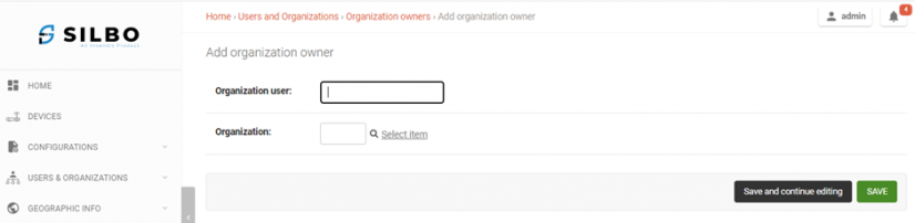
4.3.1 Creating New Organization Owner
Click on the “+ADD ORGANIZATION OWNER” button on the right-hand side.
Enter the configuration details such as New_Organization_UserName, Organization as shown in Figure-4.3.1.
Click on “Save and continue editing” or “Save” button.Figure-4.3.1: Add Organization Owner
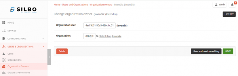
4.3.2 Edit Existing Organization Owner
Click on the “GET USER” Name to edit the configurations.
Update the configuration details as shown in Figure-4.3.2.
Click on “Save and continue editing” or “Save” button.Figure-4.3.2: Edit Organization Owner
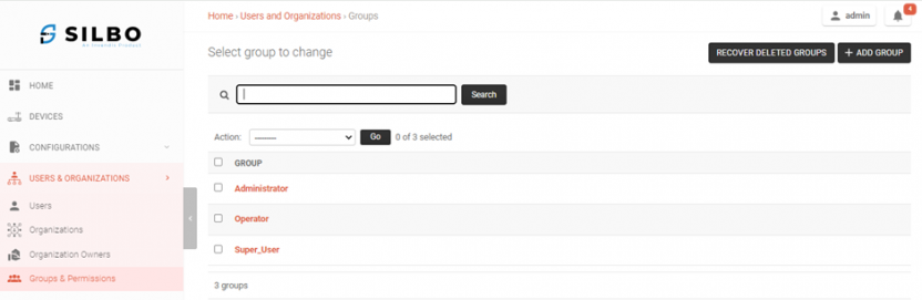
4.4 Groups and Permissions
Navigate to Users & Organizations and Select option Groups & Permissions on the left-hand side.
The Groups & Permissions page looks as shown in Figure-4.4.Figure-4.4: Groups & Permissions
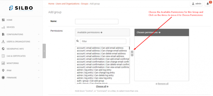
4.4.1 Creating New Group
Click on the “+ADD GROUP” button on the right-hand side.
Enter the configuration details such as Name and choose the available permissions you need for this Group as shown in Figure-4.4.1.
Click on “Save and continue editing” or “Save” button.Figure-4.4.1: Add Group
4.4.2 Edit Existing Group
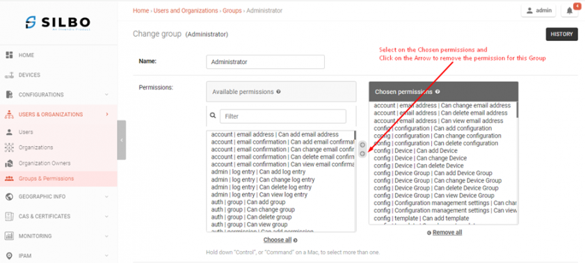
Click on the “Group” Name to edit the configurations.
Update the configuration details as shown in Figure-4.4.2.
Click on “Save and continue editing” or “Save” button.Figure-4.4.2: Edit Group
5. Geographic Info
Here the Geographical Information can be updated which are applicable for all Site devices.
5.1 Locations
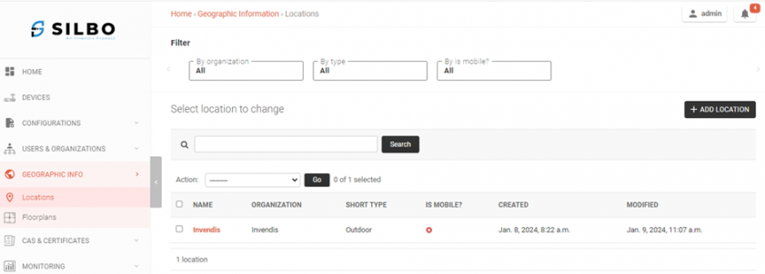
Navigate to Geographic Info and Select option Locations on the left-hand side.
The Locations page looks as shown in Figure-5.1.Figure-5.1: Locations
5.1.1 Adding New Location
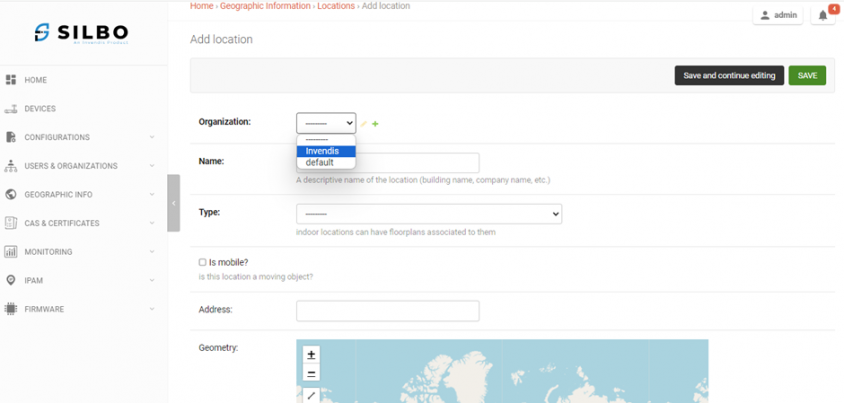
Click on the “+ADD LOCATION” button on the right-hand side.
Enter the configuration details such as Organization, Name, Type, Address as shown in Figure-5.1.1.
Click on “Save and continue editing” or “Save” button.Figure-5.1.1: Add Location
5.1.2 Edit Existing Location
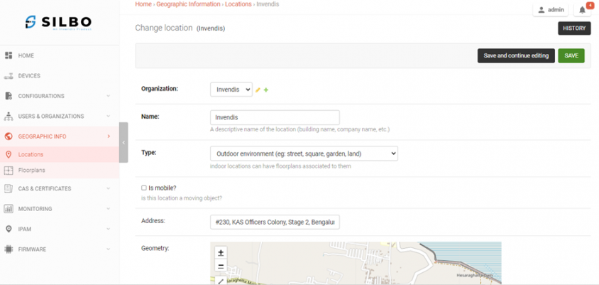
Click on the “Name” to edit the configurations.
Update the configuration details as shown in Figure-5.1.2.
Click on “Save and continue editing” or “Save” button.Figure-5.1.2: Edit Location Details
6. Firmware
Here the Firmware Management related can be updated which are applicable for all Site devices.
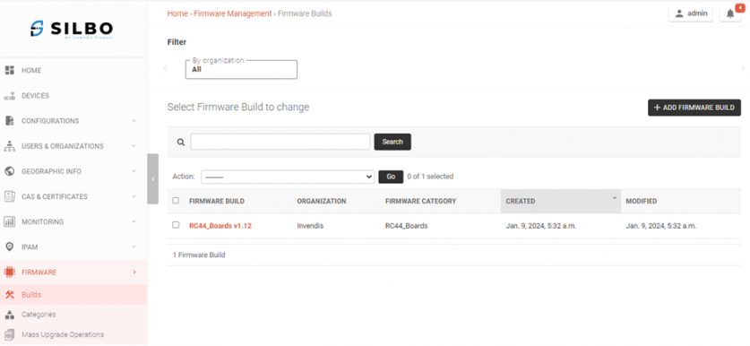
6.1 Builds
Navigate to Firmware and Select option Builds on the left-hand side.
The Firmware Builds page looks as shown in Figure-8.1.Figure-8.1: Firmware Builds
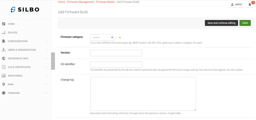
6.1.1 Adding New Firmware Build
Click on the “+ADD FIRMWARE BUILD” button on the right-hand side.
Enter the configuration details such as Firmware Category, Version.
Click on “Add another Firmware Image” by scrolling and choose the file to upload as shown in Figure-8.1.1a & 8.1.1b.
Click on “Save and continue editing” or “Save” button.Figure-8.1.1a: Add Firmware Build Details
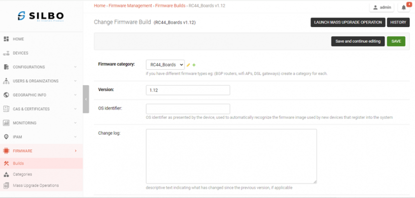
6.1.2 Edit Existing Firmware Build
Click on the “Firmware Build” Name to edit the configurations.
Update the configuration details and upload the firmware Image file as shown in Figure-8.1.2a.
Click on “Save and continue editing” or “Save” button.Figure-8.1.2a: Edit Firmware Build Details
Also, you can do Mass Upgradation Operation from this page.
Click on the “Launch Mass Upgradation Operation” on top-right corner.
Then Click on Upgrade all devices as shown in Figure-8.1.2b.
Note: Ensure the Firmware Image upload is the correct one.
Figure-8.1.2b: Add Firmware Build Details
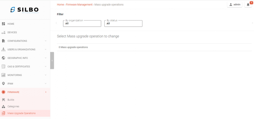
6.2 Mass Upgrade Operations
Navigate to Firmware and Select option Mass Upgrade Operations on the left-hand side.
The Mass Upgrade Operations page looks as shown in Figure-8.2a. Figure-8.2a: Mass Upgradation Operation
Click on the “By Organization” and “By Status” Filters and choose the proper input to display the Mass Upgradation Operation details as shown in Figure-8.2b.Figure-8.2b: Mass Upgradation Operation Filters