GRD44B-5R User Manual
Connecting with the device to the System (Laptop/Desktop)
To log in to SILBO_GRD44B-5R by connecting the router to your laptop or desktop via LAN or using Wi-Fi, please follow the steps below.
Connecting via LAN:
Connect your laptop's LAN port to one of the router's LAN interfaces. Ensure that you select any LAN interface (there are 4 available) while making sure the WAN interface is not used.
How to connect with the SILBO_ GRD44B-5R application
Once the LAN connection is established between the device and the laptop or the desktop
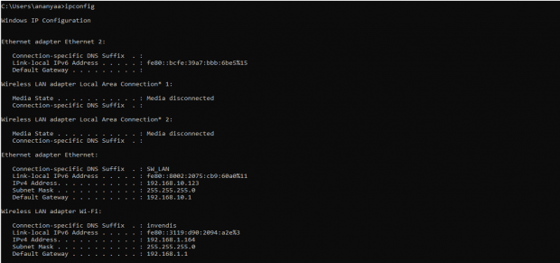
Please open the command prompt and ping to get the IP config of that device.
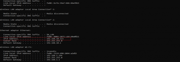
Type the command Ipconfig
It will provide the Ip address/url of that device through which the application can be accessed.
Log In
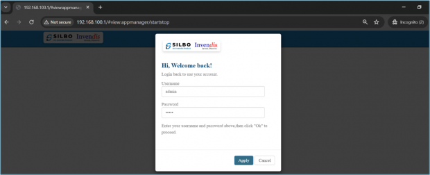
Open the web browser and type the IP address in the URL.
It will show the log in page of the application.
Give the valid credentials for the username and password to login to the application page.
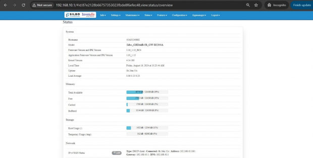
Once the user credentials are provided it will direct to the landing page of the application.
The “Status” landing page shows all the detailed specification of the device like system, memory storage and connection tracking etc.
The application is divided in to 8 Modules.
- Info
- Settings
- Maintenance
- Status
- Features
- Configuration
- Appmanager
- Logout
1. Info
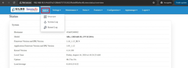
The “Info” module provides the information about the devices to the user.
It provides all the specification related to the hardware, firmware, Networks and the Connection uptimes.
It has 3 submodules.
- Overview
- System Log
- Kernel Log
1.1 Overview
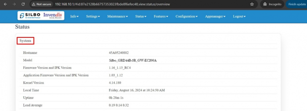
In overview module it displays all the specification categorically of a device like System, Memory, storage, Connection tracking, DHCP Lease.
System:
In this section it displays the hardware configured specification of the device.
The specifications details are as follows,
| SN | Field name | Sample value | Description |
| 1 | Hostname | 45A05240882 | This field displays the router serial number of the device |
| 2 | Model | Silbo_GRD44B-5R_GW-EC200A | This field displays the model number of the device |
| 3 | Firmware Version and IPK Version | 1.16_1.13_RC4 | This field displays the firmware version and IPK version |
| 4 | Application Firmware version and IPK version | 1.03_1.12 | This field displays the software version of the device. |
| 5 | Kernel Version | 4.14.180 | This field displays the kernel version of the device |
| 6 | Local Time | Friday, July 19, 2024 at 11:52:23 AM | This field displays the local time |
| 7 | Uptime | 1h 48m 3s | This field displays the uptime of the device |
| 8 | Load Average | 0.66 0.29 0.17 | This field displays the average load |
Memory:
In this section it displays the memory configured specification of the device.
The specifications details are as follows.
| SN | Field name | Sample value | Description |
| 1 | Total Available | 57716 kB / 124188 kB (46%) | This field displays the total availability of memory space in the device |
| 2 | Free | 46424 kB / 124188 kB (37%) | This field displays the Free memory space in the device |
| 3 | Cached | 444 kB / 124188 kB (0%) | This field displays the Cached memory space in the device |
| 4 | Buffered | 11224 kB / 124188 kB (9%) | This field displays the Buffered memory space in the device |
Storage:
In this section it displays the status of storage as root and temporary usage specification of the device.
The specifications details are as follows.
| SN | Field name | Sample value | Description |
| 1 | Root Usage | 1580 kB / 12800 kB (12%) | This field displays the total root usage of the device |
| 2 | Temporary Usage | 444 kB / 62092 kB (0%) | This field displays the total temporary usage of the device |
Network:
In this section you can monitor IPv4 WAN status.
The specifications details are as follows.
| SN | Field Name | Sample value | Description |
| 1 | Type | DHCP client | A DHCP client is a device or software that requests and receives configuration information from a DHCP server, such as an IP address, gateway, and DNS servers. |
| 2 | Connected | 1h 49m 8s | This indicates the duration for which the device has been connected to the network. |
| 3 | Address | 10.62.35.111 | This is the IP address assigned to the DHCP client by the DHCP server. It uniquely identifies the device on the network. |
| 4 | Gateway | 10.62.35.144 | The gateway (or default gateway) is the IP address of the network device that routes traffic from the local network to other networks. |
| 5 | DNS | 8.8.8.8, 10.103.81.232 | The first DNS server "8.8.8.8" is a public DNS server provided by Google.
The second DNS server "10.103.81.232" is a private DNS server. |
Active SIM Information:
This section displays SIM details only when the SIM card is active.
Connection Tracking:
In this section it displays the status of connection tracking for the device.
The specifications details are as follows.
| SN | Field Value | Sample Value | Description |
| 1 | Active Connections | 48/16384 (0%) | This field displays the active connection of the device. |
DHCP Leases:
In this section it displays the DHCP lease of the temporary assignment of an IP address to a device on the network.
The specifications details are below.
| SN | Field name | Sample value | Description |
| 1 | Host Name | KermaniK-LT | This field displays the configured Host Name/Username for that device. |
| 2 | IPv4-Address | 192.168.10.147 | This field displays the IP address of the device. |
| 3 | MAC-Address | 34:73:5a:bb: ab:7a | This field displays the MAC-Address of the device. |
| 4 | Lease time remaining | 11h 53m 49s | This field displays the lease time remaining for the device. |
1.2 System Log
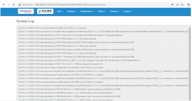
This page provides on screen System logging information. In this page the user gets to view the system logs.
1.3 Kernel Log
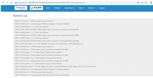
This page provides on screen Kernel logging information.
In this page the user gets to view the Kernel logs.
2. Setting
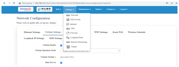
In this “Setting” module the user can Configure/update all the required parameters related to Network, SIM Switch, Internet, VPN, Firewall, Loopback Rule, Remote monitoring, Tunnel as per requirement.
IT consist of 8 submodules.
- Network
- Sim Switch
- Internet
- VPN
- Firewall
- Loopback Rule
- Remote Monitoring
- Tunnel
2.1 Network
In this section the user does all the setting related configuration with reference to network like Ethernet Setting, Cellular Setting, Band lock and Operator Lock, Wi-Fi, Guest Wi-Fi, Wireless Schedule, SMS Setting, Loopback IP.
Ethernet Setting:
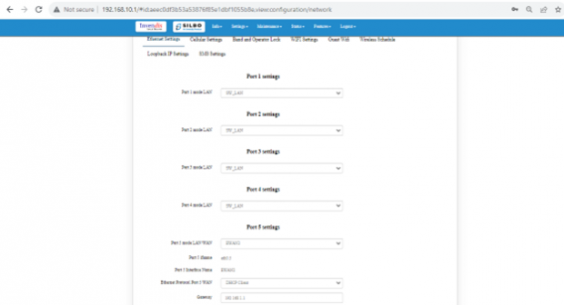
In this page it will display all the configured port that is attached with the device.
For this device 5 ports are configured. Ethernet mode can be configured as WAN and as LAN as well. Ethernet LAN Connection settings can be configured as DHCP server or Static.
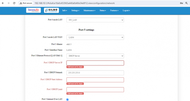
For port 5 settings,
Kindly select the option LAN for Port 5 mode LAN/WAN. Based on the option selected the field will also change. The user needs to configure all the required field and click on save.
| SN | Field name | Sample value | Description |
| 1 | Port 5 mode LAN/WAN | LAN | This field displays the port mode selection |
| 2 | Port 5 Ethernet Protocol [LAN Eth0.1] | 1.) DHCP Server
2.) Static |
This field displays the Ethernet mode selection |
| 3 | Port 5 DHCP Server IP
Port 5 Static IP |
1.) 192.168.10.1
2.) 5.6.7.8 |
This field displays DHCP server and static IP configured. |
| 4 | Port 5 DHCP and Static Netmask | 255.255.255.0 | This field displays DHCP server and static Netmask address configured |
| 5 | Port 5 DHCP Start Address | 100 | This field displays DHCP server start address configured |
| 6 | Port 5 DHCP Limit | 50 | This field displays DHCP server limit |
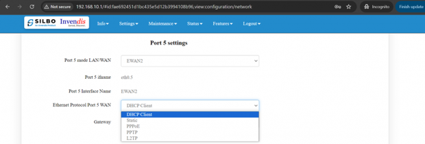
Kindly select the option EWAN2 for Port 5 mode LAN/WAN. Based on the option selected the field will also change. The user needs to configure all the required field and click on the save to save the required fields.
The specifications details are below.
| SN | Field name | Sample value | Description |
| 1 | Port 5 mode WAN | EWAN2 | This field displays the port mode selection |
| 2
|
Ethernet Protocol Port 5 WAN | 1.) DHCP client
2.) Static 3.) PPPoE 4.) PPTP 5.) L2TP |
1.) Automatically obtains IP address and network configuration from a DHCP server.
2.) Manually set a fixed IP address and network configuration. 3.) Point-to-Point Protocol over Ethernet, used for connecting to DSL services. 4.) Point-to-Point Tunnelling Protocol, used for establishing VPN connections. 5.) Layer 2 Tunnelling Protocol, another VPN protocol option. |
| 3 | Gateway | 192.168.1.1 | This field displays gateway address configured |
Click on the save once all the configuration is done and click on the update button to update all the information.
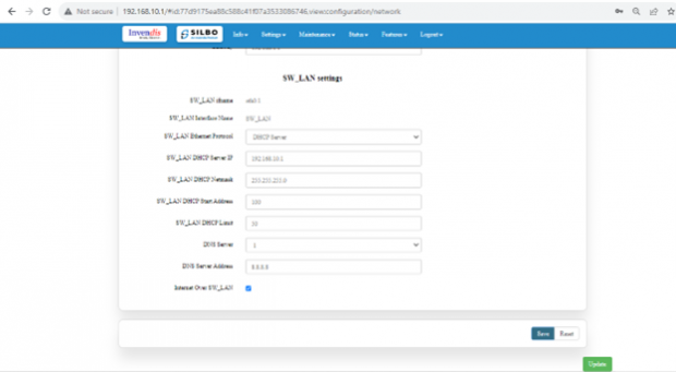
SW_LAN settings,
In this part the user can configure the setting for SW_LAN.
Note: After any changes made, save and update the page below.
The specifications details are below.
| SN | Field name | Sample value | Description |
| 1 | SW_LAN Ethernet Protocol | DHCP Server | This field displays the Ethernet mode selection. |
| 2 | SW_LAN DHCP Server IP | 192.168.10.1 | This field displays DHCP server IP configured which can be changed accordingly. |
| 3 | SW_LAN DHCP Netmask | 255.255.255.0 | This field displays DHCP server Netmask address configured. |
| 4 | SW_LAN DHCP Start Address | 100 | This field displays DHCP server start address configured. |
| 5 | SW_LAN DHCP Limit | 50 | This field displays DHCP server limit. |
| 6 | DNS Server | 1 | This filed display number of DNS server availability. |
| 7 | DNS Server Address | 8.8.8.8 | This filed display the DNS server address. |
After configuring all the required information, the user should click on the save and then click on the update to update the all the required information.
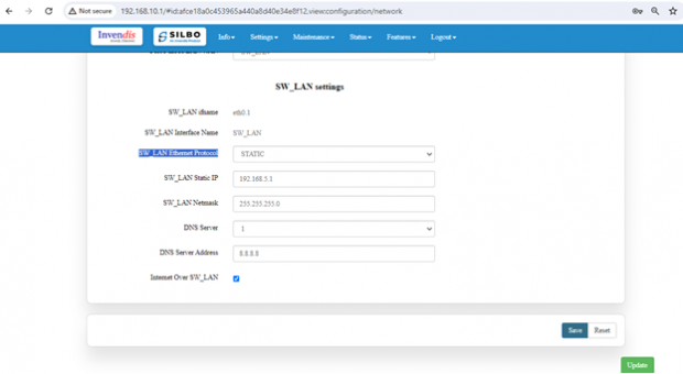
Static option for SW_LAN Ethernet Protocol:
Select the option of static from the drop-down menu for SW_LAN Ethernet Protocol.
Note: After any changes made, save and update the page below.
The specifications details are below.
| SN | Field name | Sample value | Description |
| 1 | SW_LAN Ethernet Protocol | Static | This field displays the Ethernet mode selection |
| 2 | SW_LAN static IP | 192.168.5.1 | This field displays static server IP configured. |
| 3 | SW_LAN Netmask | 255.255.255.0 | This field displays static server Netmask address configured |
| 4 | DNS Server | 1 | This filed display number of DSN server availability |
| 5 | DSN Server Address | 8.8.8.8 | This filed display the DSN server address. |
After configuring all the required information, the user should click on the save and then click on the update to update the all the required information.
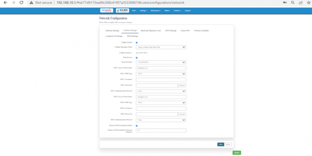
Cellular Setting:
In this page, the user needs to configure the various details with respect to the SIM.
Select single cellular single sim where the user must configure the APN details of the sim used for the router device. The Configurations can be done based on the SIM usage, with respect to IPV4 or IPV6.
| SN | Field name | Sample value | Description |
| 1 | Cellular Enable | Checkbox | Check this box to enable cellular functionality. |
| 2 | Cellular Operation Mode | 1.) Single Cellular with Dual Sim
2.) Single Cellular with Single SIM |
1.) This mode allows you to use one cellular modem with two SIM cards.
2.) This mode allows you to use one cellular modem with single SIM card. |
| 3 | Cellular Modem 1 | QuectelEC200A | This field displays the modem name. |
| 4 | Choose SIM 1 APN Mode | 1.) Auto
2.) Manual |
1.) Choose Auto for regular SIM to detect APN name automatically.
2.) Choose manual to enter the APN settings manually in case of M2M SIM cards. |
| 5 | SIM 1 Access Point Name | airtelgprs.com | Enter the APN provided by your cellular service provider in case of M2M sim. For regular sim cards APN name will be displayed automatically. |
| 6 | SIM 1 PDP Type | IPV4 | Choose the PDP type, which is typically either IPv4 or IPv6 depending on the sim card. |
| 7 | SIM 1 Username | Enter the username if required by the APN. Leave blank if not required. | |
| 8 | SIM 1 Password | Enter the password if required by the APN. Leave blank if not required. | |
| 9 | SIM 1 Authentication Protocol | None | Choose the authentication protocol. Options typically include None, PAP, or CHAP. |
| 10 | Choose SIM 2 APN Mode | 1.) Auto
2.) Manual |
1.) Choose Auto for regular SIM to detect APN name automatically.
2.) Choose manual to enter the APN settings manually in case of M2M SIM cards. |
| 11 | SIM 2 Access Point Name | airtelgprs.com | Enter the APN provided by your cellular service provider in case of M2M sim. For regular sim cards APN name will be displayed automatically. |
| 12 | SIM 2 PDP Type | IPV4 | Choose the PDP type, which is typically either IPv4 or IPv6 depending on the sim card. |
| 13 | SIM 2 Username | Enter the username if required by the APN. Leave blank if not required. | |
| 14 | SIM 2 Password | Enter the password if required by the APN. Leave blank if not required. | |
| 15 | SIM 2 Authentication Protocol | None | Choose the authentication protocol. Options typically include None, PAP, or CHAP. |
| 16 | Primary SIM Switchback Time (In Minutes) | 10 | Enter the time in minutes after which the system should switch back to the primary SIM if it becomes available. |
After configuring all the required information, the user should click on the save and then click on the update to update the all the required information.
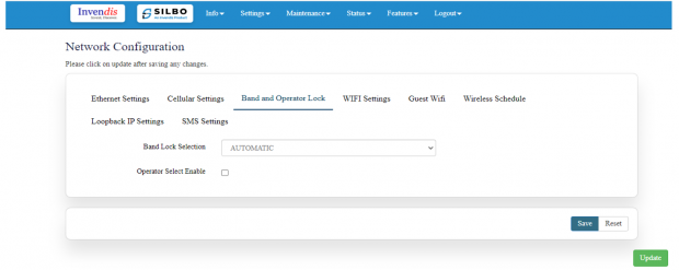
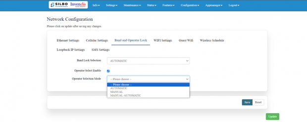
Band lock and Operator Lock:
In this page, the user needs to configure the lock band and operator based on the service provider.
Bands available in the drop-down list.
2G/3G option:
2G/3G: - 3G allows additional features such as mobile internet access, video calls and mobile TV. While the main function of 2G technology is the transmission of information through voice calls.
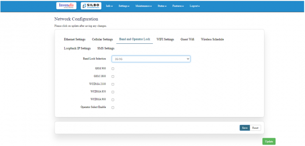 The user should select the band check box available for 2g/3g from the given list. Bands available for selection under LTE for the bands available in that area.
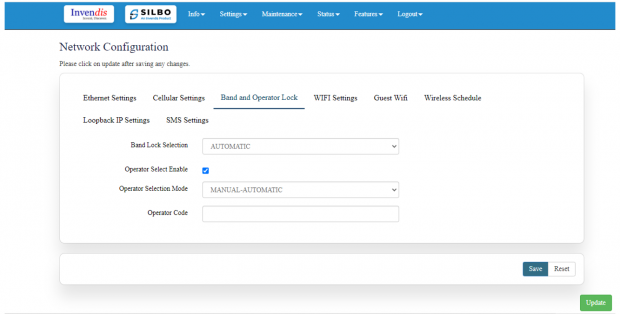
Operator Selection Mode:
The user needs to click on the check box of the “operator select enable” to select the operator.
Once the check box is clicked there will be a dropdown list of the operator modes from which the user needs to select the mode. The user needs to select the operator mode from the given dropdown list.
If the user selects the mode “Manual” or “Manual-Automatic” then one more text box will appear where the user must provide the operator code.
After configuring all the required information, the user should click on the save and then click on the update to update the all the required information.
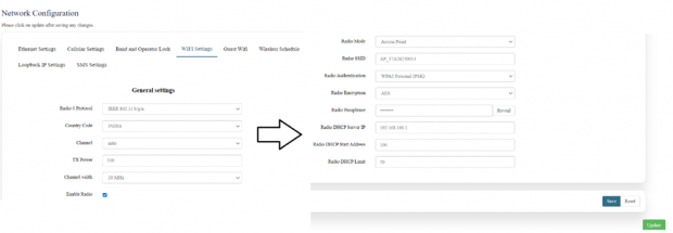
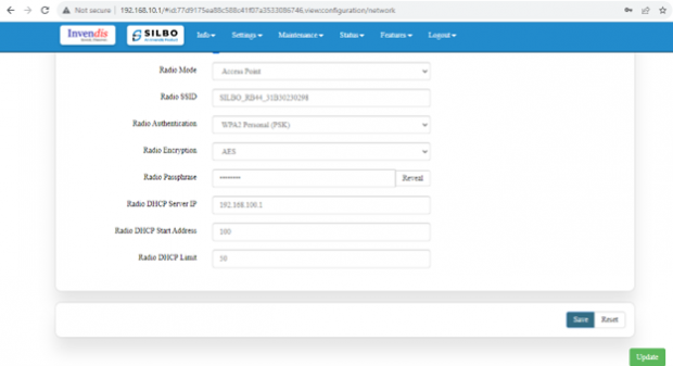
Wi-Fi Setting:
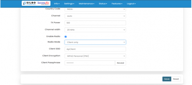
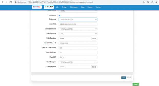
In this, router has the general setting and change country code, channel, radio mode, radio passphrase as per the requirement after clicking on enable Radio button.
The user needs to select the respective radio mode based on its need.
It has 3 radio modes.
Access point
Client only
Access point and client
Access Point mode:
In Access Point mode, a configuration in which a router, allows wireless devices to connect to a wired network by creating a Wi-Fi hotspot.
Client point: In client mode, the access point connects your wired devices to a wireless network. This mode is suitable when you have a wired device with an Ethernet port and no wireless capability, for example, a smart TV, Media Player, or Game console and you want to connect it to the internet wirelessly, select the Client Mode and give the Radio SSID & client passphrase.
Access point and client point:
Select this option for both type of connection, give both SSID and passphrase.
After configuring all the required information, the user should click on the save and then click on the update to update the all the required information.
The specifications details are below.
| SN | Field name | Sample value | Description |
| 1 | Radio 0 Protocol | IEEE 802.11 b/g/n | This section shows the radio protocol which is by default. |
| 2 | Country Code | INDIA | Select the country accordingly.
(INDIA by default) |
| 3 | Channel | Auto | In this dropdown the user should select the proper channel to be used. (Auto by default) |
| 4 | TX Power | 100 | In this text box the user should specify the power. |
| 5 | Channel Width | 20 MHz | In this dropdown the user should select the channel width |
| 6 | Radio Mode | 1.) Access point
2.) Client only 3.) Access point and client |
In this drop down the user should select the mode.
(Access point by default) |
| 7 | Radio SSID | AP_37A26230014 | In this text box the user should specify the SSID number which usually comes with the router. |
| 8 | Radio Authentication | WPA2 Personal (PSK) | In this dropdown the user should select the type of authentication.
(WPA2 Personal (PSK) by default) |
| 9 | Radio Encryption | AES | In this dropdown the user should select the type of encryption required.
(AES by default) |
| 10 | Radio Passphrase | ********* | In this text box the user should specify the password. Password will be given with the router which can be changed later. |
| 11 | Radio DHCP server IP | 192.168.100.1 | In this text box the user should specify the IP address of DHCP server.
(192.168.100.1 will be default which can be changed accordingly) |
| 12 | Radio DHCP start address | 100 | In this text box the user should specify the start address of the DHCP.
(100 value is default) |
| 13 | Radio DHCP limit | 50 | In this text box the user should specify the limit for the DHCP.
(50 value is default) |
Click on save once changes have been made.
Wireless Schedule:
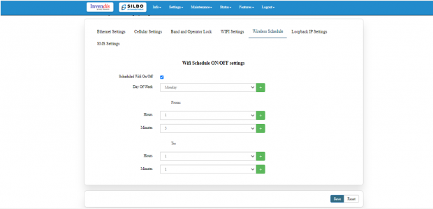
Wi-Fi can be automatically withdrawn based on the configuration done in this section.
The user can schedule the Wi-Fi’s accessibility time during a particular period.
Note: This section is turned off by default, tick the box to activate it.
After configuring all the required information, the user should click on save and then click on update to update all the required information.
The user can select more than one “day of the week” for scheduling the Wi-Fi working hours.

