In this guide, Modbus TCP to MQTT function will be configured using third-party MQTT broker services (in this example https://www.hivemq.com/).
The Router will be used as TCP Master and MODSIM (application) will be used as TCP slave.
PC will act as MQTT Publisher and Subscriber.
2. Prerequisites:
Connecting board to device: Connect your router to your device via
Ethernet cable: Directly connect router port with RJ45 wire to your device.
Wireless network connection: Connect router to your device using Wi-Fi, check device name and password on the device’s label. For Example: SSID: APClient_37B11241001 PWD: 12345678
3. Login to device:
To enter the router’s Web interface (web IU), type 192.168.100.1 (wireless LAN IP) into the URL field of your internet browser.
Use the following login information when prompted for authentication. Username: admin
Login to device
4. Configure Modbus TCP Slave (MODSIM): Download and Open MODSIM:
Click on File
New
Address: Start bit address
Length: No of registers to be read
Select based on parameters to read
Device Id: Set Slave ID
Connect to Modbus TCP service port
TCP port : 502
Click ok
*Modbus TCP Slave (MODSIM) has been configured*
5. Configure Modbus TCP Master (Router):
After login, go to configuration=> Modbus configuration,
1. Click on Add Device
Configure Modbus TCP Master
2. Parameters Configuration:
*Refer the table below for input details*
Field
Value
Description
Device Name
Invendis
Any name of your choice.
Port no
1.) RS485 Port-1
2.) RS232 Port-2
Depending on the port that is available on your router.
Meter ID
Default = 1
Can change as per your device.
Meter Model
abcd
Any name of your choice.
Function code
Read coils (1)
Read input coils (2)
Read holding registers (3)
Read input registers (4)
Specifies the type of register being addressed by Modbus request.
Slave Address
1
According to the device connected to poll data, slave ID is mentioned.
If you want to add additional parameters in single slave Address Option 1: Default mapping Option 2: Custom mapping
Field
Value
Description
Default mapping
1.) Tag Name = (Ex: FQ)
2.) Data type = 8bit INT | 8bit UINT | 16bit INT, high byte first | 16bit INT, low byte first | 16bit UINT, high byte first | 16bit UINT, low byte first | 32bit float (various Byte order) | 32bit INT (various Byte order) | 32bit UINT (various Byte order) | 1 bit; default: Hexadecimal
1.) Input value name.
2.) Defines how read data will be stored.
Custom mapping
1.) Register name:
2.) Start register:
3.) Register count:
4.) Data type = 8bit INT | 8bit UINT | 16bit INT, high byte first | 16bit INT, low byte first | 16bit UINT, high byte first | 16bit UINT, low byte first | 32bit float (various Byte order) | 32bit INT (various Byte order) | 32bit UINT (various Byte order) | 1 bit; Hexadecimal; default: 32-bit floating point
1.) Input value name.
2.) First register in custom register block.
3.) Path to file in which the custom register block will be stored.
4.) Defines how read data will be stored.
*Modbus TCP Master (router) has been configured*
6. Cloud Configuration (MQTT Gateway) on Modbus TCP Master:
Open routers WebUI and navigate to Configuration à Cloud Configuration
Site ID: Give name accordingly
Cloud/Protocol: HTTP; MQTT; Azure à Select protocol in use
MQTT Host: Host name as per the MQTT broker selected ( in use hivemq.com)
MQTT Port: 1883 (default)
Authentication Mode: no authentication; username/password; TLS (further added procedure if selected the other two)
RS485 Topic (optional): Give a topic name and copy it
Save
Cloud Configuration (MQTT Gateway) on Modbus TCP Master
7. Configure hivemq.com MQTT Broker:
It is an open server so no need to login
Click MQTT
Public MQTT Broker
Try MQTT Browse client
Click on connect, wait until the light turns green
Click on Add new subscription
Paste the topic name copied from MQTT Gateway (refer cloud configuration)
Click on subscribe
*MQTT Broker is ready to publish data*
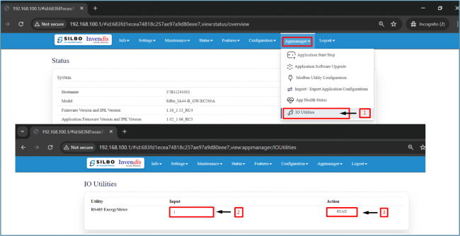
8. Testing MQTT Publisher and Subscriber on hivemq.com:
Navigate to Appmanagerà ->IO Utilities
Enter Slave ID assigned (in this example slave id = 1)
Click Read to generate output.Testing MQTT Publisher and Subscriber on hivemq.com: Click Read to generate output.
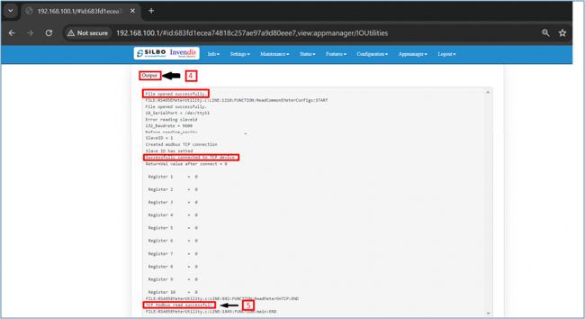
Output
Once you see “TCP Modbus read successful” we can publish data on hive MQTT.TCP Modbus read successful” we can publish data on hive MQTT.
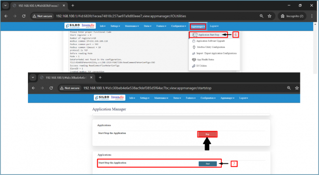
Navigate to Appmanager à Application start/stop
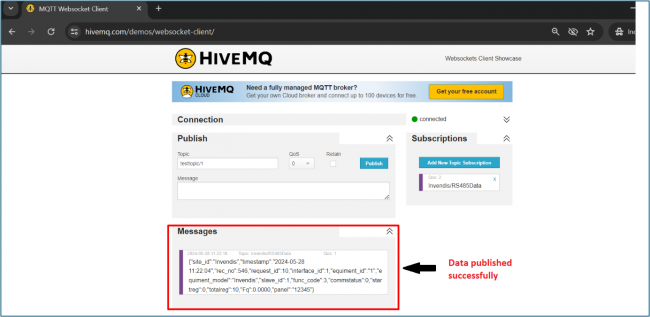
click on start, wait until the sign turns to stopTesting MQTT Publisher and Subscriber on hivemq.com-click on start, wait until the sign turns to stopOpen Hivemq.com and data should start publishing, this means that MQTT Gateway on Modbus TCP Master router is working correctly, and Modbus TCP Slave receives requestHive Mq


-Register_config.png)
_on_Modbus_TCP_Master.png)